SPECIFICATIONS
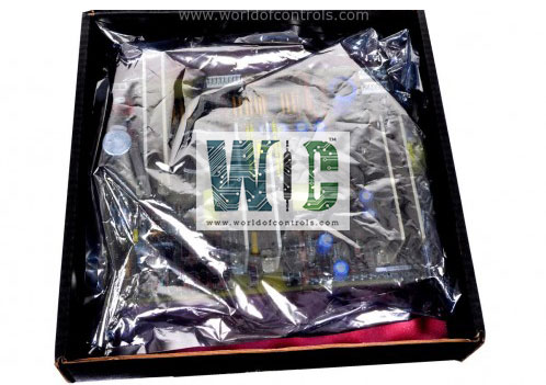
Part No.: IS215VCMIH1A
Manufacturer: General Electric
Country of Manufacture: United States of America (USA)
Temperature Operating: -30 to 65 oC
Board Type: 6U high VME board
Size: 0.787 inch wide
Processor: TMS320C32
Memory: Dual-port memory
SRAM: 64k x 32
Flash memory: 128k x 8
Availability: In Stock
Series: Mark VI
Functional Description
IS215VCMIH1A is a Bus Master Controller developed by GE. It is part of Mark VI control system. The VCMI (VME Communication Module Interface) serves as an interface between the controller and I/O boards, as well as the system control network, known as IONet. It plays a central role in facilitating data exchange between the control system and various components, ensuring that all modules within the system communicate effectively.
Features and Capabilities
- VME Bus Master Functionality: Operates as the primary communication controller (bus master) for all boards within the VME rack. Manages communication timing, synchronization, and priority across multiple connected modules. Ensures orderly and collision-free data exchange between control and I/O components.
- Module Identification Management: Automatically detects and manages the identification (ID) of each board in the rack. Ensures that all boards are properly recognized and uniquely addressed within the system. Prevents communication conflicts or duplication errors during system operation or startup.
- IONet Communication: Interfaces directly with IONet, the dedicated control network of the Mark VI system. Enables high-speed data exchange between control racks, turbine controllers, and operator stations. Supports redundant network configurations (dual IONet) to maintain system integrity in case of link failures.
- Data Coordination and Timing Control: Oversees the timing and control signals that synchronize operations between the various boards. Ensures that critical control loops, protection logic, and data logging processes remain precisely aligned. Maintains communication consistency even under heavy data loads or transient disturbances.
- System Diagnostics and Health Monitoring; Continuously monitors communication integrity and module health. Reports diagnostic data and fault conditions to the main controller for system-level monitoring. Supports predictive maintenance by providing real-time insight into rack communication performance.
Diagnostics
The module performs ongoing diagnostics to monitor system performance, particularly regarding the power supplies and the communication interface:
- Internal Power Supply Monitoring: The 5 V, 12 V, 15 V, and 28 V power supply buses are constantly monitored for any deviations from expected values. If a power supply falls outside the acceptable range, an alarm is triggered. The alarm thresholds are configurable but are typically set to activate at a 3.5% variance for most supplies, except for the 28 V supply, which has a slightly higher variance threshold of 5.5%. This ensures that minor fluctuations are caught early and corrective actions can be taken before any significant disruptions occur.
- Power Distribution Module (PDM) Diagnostics: Diagnostic signals from the Power Distribution Module (PDM) are fed into the VCMI through connector J301. These signals provide critical information about the health and status of the power systems within the control network. Key diagnostic parameters include:
- Ground Fault Detection: Any unintentional connection between a power line and ground is detected, preventing potential damage or safety hazards.
- Over/Under Voltage Monitoring: The VCMI monitors for voltage irregularities on the P125 V bus. Both over-voltage and under-voltage conditions can indicate problems in the power supply or distribution system.
- Differential ±5 V DC Analog Inputs: Two differential inputs allow the system to measure and compare signals for more precise monitoring of power conditions or external inputs.
- External Monitor Circuits: The VCMI receives signals from external monitor circuits connected to the P28A and PCOM terminals, ensuring that external systems integrated with the control network are functioning properly.
- Digital Inputs: Various digital input signals are monitored by the VCMI to provide additional status feedback from the connected control components or other I/O devices.
The WOC team is always available to help you with your Mark VI requirements. For more information, please contact WOC.
Frequently Asked Questions
What is IS215VCMIH1A?
It is a Bus Master Controller developed by GE under the Mark VI series.
What power supply buses are monitored by VCMI?
The VCMI module monitors the internal 5 V, 12 V, 15 V, and 28 V power supply buses. These power supplies are essential for the operation of the system, and any irregularities are detected and alarmed.
What are the alarm thresholds for power supplies?
The alarm thresholds are typically configured at a 3.5 percent variance for the 5 V, 12 V, and 15 V power supplies. For the 28 V power supply, the alarm threshold is set at 5.5 percent variance. These thresholds help ensure timely detection of power irregularities.
Does the board monitor external power signals?
Yes, the VCMI monitors signals from the Power Distribution Module (PDM) through connector J301. These signals include diagnostics for ground faults, over/under voltage conditions, differential analog inputs, and more.
