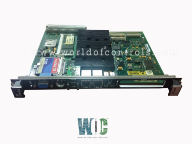
World Of Controls understands the criticality of your requirement and works towards reducing the lead time as much as possible.
IS215UCVGM01A - Universal Control Variable Generator Module is available in stock which ships the same day.
IS215UCVGM01A - Universal Control Variable Generator Module comes in UNUSED as well as REBUILT condition.
To avail our best deals for IS215UCVGM01A - Universal Control Variable Generator Module, contact us and we will get back to you within 24 hours.
SPECIFICATIONS:
Part Number: IS215UCVGM01A
Manufacturer: General Electric
Series: Mark VI
Microprocessor: Intel Celeron 650 MHz
Memory: 128 MB SDRAM
Operating system: QNX
Programming: Boolean
Product Type: Universal Control Variable Generator Module
Voltage Range: 14 to 32 V dc
Maximum Lead Resistance: 15 Ω
Storage temperature: -40 to 80° C
Operating temperature: 0 to 70° C
Technology: Surface mount
Size: 16.2 cm high x 8.6 cm
Repair: 3-7 Day
Availability: In Stock
Weight: 2 lbs
Country of Origin: United States
Manual: GEh-6421l
FUNCTIONAL DESCRIPTION:
IS215UCVGM01A is a Universal Control Variable Generator Module manufactured and designed by General Electric as part of the Mark VI Series used in GE Speedtronic Control Systems. The UCVG is a single-slot board using an Intel Ultra Low Voltage Celeron 650 MHz processor with 128 MB of flash memory and 128 MB of SDRAM. Two 10BaseT/100BaseTX (RJ-45 connector) Ethernet ports provide connectivity. The first Ethernet on the UCVG allows connectivity to the UDH for configuration and peer-to-peer communication. The second Ethernet on the UCVG is for a separate IP logical subnet and can be used for Modbus or private EGD network. Configuration of the second Ethernet port is performed through the toolbox. The controller validates its toolbox configuration against the existing hardware each time the rack is powered up.
OPERATION:
The controller is loaded with software specific to its application to steam, gas, and land-marine aero-derivative (LM), or balance of plant (BOP) products. It can execute up to 100,000 rungs or blocks per second, assuming a typical collection of average-size blocks. An external clock interrupt permits the controller to synchronize with the clock on the VCMI communication board to within ± 100 microseconds.
External data is transferred to and from the control system database (CSDB) in the controller over the VME bus by the VCMI communication board. In a simplex system, the data consists of the process inputs and outputs from the I/O boards. In a TMR system, the data consists of the voted inputs from the input boards, singular inputs from simplex boards, computed outputs to be voted by the output hardware and the internal state values that must be exchanged between the controllers.
INSTALLATION:
A control module contains (at a minimum) the controller and a VCMI. Three rack types can be used, the GE Fanuc integrator’s rack shown in the following figure, and two sizes of Mark VI racks shown in the section, VCMI - Bus Master Controller. The GE Fanuc rack is shorter and is used for stand-alone modules with remote I/O only. The Mark VI racks are longer and can be used for local or remote I/O. Whichever rack is used, a cooling fan is mounted above or below the controller. The stand-alone control module implemented with a GE Fanuc integrator’s rack also requires a VDSK board to supply fan power and identify the rack through an ID plug.
WOC has the largest stock of OEM Replacement Parts for GE Speedtronic Gas Turbine Control Systems. We can also repair your faulty boards and supply unused and rebuilt boards backed up with a warranty. Our team of experts is available round the clock to support your OEM needs. Our team of experts at WOC is happy to assist you with any of your automation requirements. For pricing and availability on parts and repairs, kindly contact our team by phone or email.
What is the Universal Control Variable Generator (UCVG) Module used for?
The UCVG Module is used in General Electric's Mark VI turbine control system, which manages gas and steam turbines in power generation and other industrial applications. It handles real-time data processing, runs control algorithms, and communicates with various subsystems and external control systems to ensure the safe and efficient operation of turbines.
What processor is used in the UCVG module?
The UCVG uses an Intel Ultra Low Voltage Celeron 650 MHz processor, paired with 128 MB of flash memory and 128 MB of SDRAM, to handle its processing needs.
What is the purpose of the Ethernet ports on the UCVG module?
The UCVG module has two Ethernet ports. The first Ethernet port is used for connectivity to the UDH (Unit Data Highway), facilitating configuration and peer-to-peer communication. The second Ethernet port is typically used for Modbus or private EGD (Ethernet Global Data) networks, connecting the UCVG to separate IP logical subnets for advanced communication.