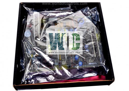
IS210TREAH1A - Turbine Emergency Trip Terminal Board

IS210TREAH1A - Turbine Emergency Trip Terminal Board IS210TREAH1A - Turbine Emergency Trip Terminal Board

World Of Controls understands the criticality of your requirement and works towards reducing the lead time as much as possible.

IS210TREAH1A - Turbine Emergency Trip Terminal Board is available in stock which ships the same day.

IS210TREAH1A - Turbine Emergency Trip Terminal Board comes in UNUSED as well as REBUILT condition.

To avail our best deals for IS210TREAH1A - Turbine Emergency Trip Terminal Board, contact us and we will get back to you within 24 hours.

SPECIFICATIONS

Part No.: IS210TREAH1A
Manufacturer: General Electric
Country of Manufacture: United States of America (USA)
Size: 33.0 cm high x 17.8 cm, wide
Technology: Surface mount
Temperature: -30 to 65oC
MPU pulse rate range: 2 Hz to 20 kHz
MPU pulse rate accuracy: 0.05 percent of reading
Number of inputs: 14
Number of outputs: 9
Contact ratings: NEMA class F.
Product Type: Turbine Emergency Trip Terminal Board
Availability: In Stock
Series: Mark VIe

Functional Description

IS210TREAH1A is an Aero derivative Turbine Emergency Trip Terminal Board developed by GE. It is a part of the Mark VIe control system. When combined with the WREA option card, this terminal board interfaces with PPRA turbine I/O packs to facilitate critical turbine emergency operations. It supports inputs from two 24-point pluggable barrier terminal blocks and six passive pulse rate devices that measure turbine speed using a toothed wheel mechanism.

Inputs and Outputs

The terminal board is engineered to interface with turbine systems through a robust set of input and output channels. These channels enable real-time monitoring, control logic processing, and emergency trip execution, ensuring safe and efficient turbine operation.

  • Customer Input Terminals: The board features two 24-point pluggable barrier terminal blocks—either H1A or S1A versions. These terminals are designed to accept a variety of external input signals, such as discrete contact closures, instrumentation signals, and status feedback from auxiliary systems. This configuration allows for flexible integration with customer-specific turbine applications and facilitates field wiring without the need for extensive modifications.
  • Speed Sensing Inputs: The terminal board supports six passive pulse rate inputs, enabling speed sensing from up to three turbine shafts, with two sensors per shaft for redundancy. These speed sensors operate using a toothed wheel mechanism, where each tooth generates a pulse as it passes a magnetic pickup or similar sensor. The high-resolution speed data is critical for functions such as overspeed protection, shaft synchronization, and rotational diagnostics.
  • Emergency Trip Outputs: The board is equipped with three 24 V DC solid-state output contacts that serve as TMR (Triple Modular Redundancy) voted trip outputs. These outputs are used to initiate an emergency turbine trip when a fault or unsafe condition is detected, ensuring rapid and fail-safe shutdown. Designed to operate with high reliability, these outputs support deterministic execution of trip logic to prevent damage or hazardous events.

Installation Process

Mounting the WREA Option Card

The option card is pre-mounted to the TREA terminal board at the factory. However, if servicing or reinstallation is required, the following steps must be followed:

  • Aligning the Boards: Align the connectors on the WREA card with those on the TREA board. The bottom of the WREA is identified by a row of configuration jumpers. The connectors are keyed to ensure proper alignment.
  • Securing the Connection: Firmly press on the four screw heads surrounding the connector to seat the WREA card fully. The connection is considered secure when the WREA cannot be pushed further.

Wiring the Board

For different variants of the board, connections must be appropriately configured:

  • Voltage Detection, Trip Contacts, and Relay Outputs: Wired to the I/O terminal block TB1.
  • Passive Pulse Rate Pick-ups: Wired to terminal block TB2, which includes 24 terminals held by two screws. Support for wires up to #12 AWG.

Shield Termination

A shield termination strip, attached to the chassis ground, is located to the left of each terminal block, ensuring proper grounding and signal integrity.

Configuration

  • Jumpers JP1 and JP2 are essential for selecting the fanning of the X channel speed inputs to the Y and Z PPRA I/O packs. Their proper placement is a prerequisite for ensuring PPRA operation with the TREA and WREA components. Without these jumpers in place, the system may not function as intended.
  • The WREA jumpers, JP1 through JP12, play a crucial role in configuring the output behavior of the six-speed repeater output circuits. Jumpers JP1 through JP6 are designed to toggle between the RS–232 signal level (default) and the RS–485 signal level on the repeater outputs. Among these, JP1 through JP3 are used to configure the repeater outputs for PR1 through PR3, while JP4 through JP6 handle the configurations for PR4 through PR6.
  • Jumpers JP7 through JP12, by default, correspond to PR1 through PR6 and are essential for maintaining compatibility with PPRA systems. These jumpers should remain in their default positions when used with PPRA to ensure consistent and reliable operation.

The WOC team is always available to help you with your Mark VIe requirements. For more information, please contact WOC.

Frequently Asked Questions

What is IS210TREAH1A?
It is an Aero derivative Turbine Emergency Trip Terminal Board developed by GE under the Mark VIe series.

What inputs and outputs are supported?
The board has customer input terminals provided through two 24-point pluggable barrier terminal blocks (H1A or S1A) and three TMR-voted solid-state output contacts for reliable system trips.

What is the role of the WREA option card?
The WREA option card, mounted on the terminal board, works to configure and manage the speed input circuits and repeater outputs, enhancing the system's precision and flexibility.

How is the board installed?
The WREA option card is pre-mounted to the TREA terminal board. During servicing or replacement, the connectors on both boards must be properly aligned and pressed to secure the connection fully.

What are the jumper configurations on this board?
Jumpers JP1 and JP2 manage the fanning of speed inputs to the Y and Z PPRA I/O packs. Jumpers JP1 through JP6 select signal levels (RS-232 or RS-485), while JP7 through JP12 configure the speed repeater outputs.