SPECIFICATIONS
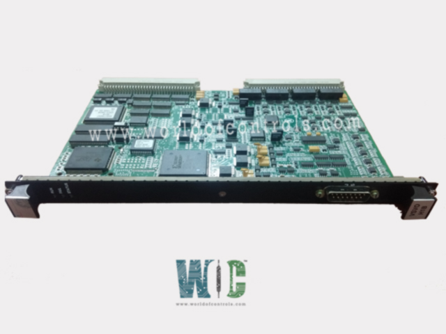
Part No.: IS200VSVOH1BDC
Manufacturer: General Electric
Country of Manufacture: United States of America (USA)
Temperature: 0 to 60 °C
Processo:r Texas Instruments TMS320C32
Product Type: Servo Control Board
Availability: In Stock
Series: Mark VI
Functional Description
IS200VSVOH1BDC is a servo control board developed by GE. It is a part of Mark VI control system. The Servo Board, designated as VSVO, serves as a critical component within the intricate tapestry of a control system, specifically tasked with the precision control of electrohydraulic servo valves. This pivotal role directly influences the actuation of steam and fuel valves, components crucial for regulating key processes in industrial and mechanical systems. Let's delve into the intricacies of the VSVO, shedding light on its functions and its seamless integration into the broader control architecture.
Features
- Control of Electrohydraulic Servo Valves: The primary function of the VSVO revolves around the precise control of four electrohydraulic servo valves. These valves play a pivotal role in modulating the flow of steam and fuel within the system, influencing critical processes such as power generation or industrial machinery operation.
- Division Across Two Servo Terminal Boards: To ensure efficient control distribution, the four channels managed by the VSVO are intelligently divided between two TSVO (Terminal Servo Output) servo terminal boards. This strategic division optimizes the allocation of control resources, contributing to the overall stability and responsiveness of the system.
Valve Position Sensing
- To ascertain the accurate position of the valves, the VSVO employs Linear Variable Differential Transformers (LVDT).
- These precision sensors provide continuous and reliable feedback on the displacement of the valves. The integration of LVDT technology ensures that the control system operates with a heightened level of accuracy and responsiveness.
Control Algorithm Execution
- Centralized Loop Control Algorithm: A distinctive feature of the VSVO is its capability to run the loop control algorithm internally. This implies that the intricate calculations and decision-making processes essential for optimal valve control are executed within the VSVO itself. This decentralized approach enhances system efficiency and minimizes communication delays, particularly in applications requiring real-time responsiveness.
- Its role in dividing control channels across TSVO servo terminal boards, utilizing LVDT for accurate valve position sensing, and executing the control algorithm internally, underscores its significance in enhancing the overall performance and reliability of the control system. As a key player in the orchestration of industrial processes, the VSVO exemplifies advanced control technologies harnessed for seamless and responsive operation.
Installation
- Power Down the VME Processor Rack: Before initiating the installation, it is imperative to power down the VME processor rack. This ensures a safe and controlled environment for the installation process, minimizing the risk of electrical interference and safeguarding both the operator and the equipment.
- Slide in the Board: With the VME processor rack powered down, carefully slide in the board into the designated slot. The slot is strategically positioned to accommodate the VSVO board seamlessly. Ensure that the insertion is precise and aligns with the slot guides to prevent any potential damage.
- Securely Seat Edge Connectors: Once the board is positioned within the slot, utilize both hands to push the top and bottom levers. This action securely seats the edge connectors, establishing a stable and reliable electrical connection with the control system. This step is critical for the board to function optimally within the system architecture.
- Tighten Captive Screws: To further enhance the stability of the VSVO board, tighten the captive screws located at the top and bottom of the front panel. This step ensures that the board is firmly secured within the rack, minimizing the possibility of vibrations or displacement during normal system operation.
- Power Up the VME Rack: Securely installed, proceed to power up the VME rack. Monitor the diagnostic indicators to confirm that VSVO board is recognized and functioning correctly. Any discrepancies observed during this phase should prompt a thorough review of the installation steps.
- Verification and Testing: Post-installation, it is prudent to conduct thorough verification and testing procedures. This involves checking the connectivity, ensuring proper alignment, and validating functionality. Any anomalies should be addressed promptly to guarantee the reliability of the entire control system.
The WOC team is always available to help you with your Mark VI requirements. For more information, please contact WOC.
Frequently Asked Questions
What is IS200VSVOH1BDC?
It is a servo control board developed by GE under the Mark VI series.
Where are the cable connections made for the TSVO terminal boards?
Cable connections for the TSVO terminal boards are established at the J3 and J4 connectors located on the lower portion of the VME rack. These connectors are of the latching type, providing a secure and reliable connection for the cables.
What is the significance of latching type connectors for cable connections?
Latching type connectors play a crucial role in ensuring the stability and security of cable connections. They feature a locking mechanism that prevents inadvertent disconnections, enhancing the overall reliability of the terminal board connections.
After making cable connections, what is the recommended next step?
Once the cable connections are securely made, the next step is to power up the VME rack. This should be done in accordance with proper startup procedures to avoid any potential issues. Subsequently, it is advised to check the diagnostic lights positioned at the top of the front panel for system status indications.
