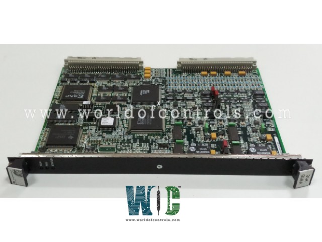
World Of Controls understands the criticality of your requirement and works towards reducing the lead time as much as possible.
IS200VRTDH1CBA - RTD Input Processor Board is available in stock which ships the same day.
IS200VRTDH1CBA - RTD Input Processor Board comes in UNUSED as well as REBUILT condition.
To avail our best deals for IS200VRTDH1CBA - RTD Input Processor Board, contact us and we will get back to you within 24 hours.
SPECIFICATIONS:
Part No.: IS200VRTDH1CBA
Manufacturer: General Electric
Series: Mark VI
Product Type: RTD Input Processor Board
Input Sensor Type: Pt100, Pt1000
Wiring Configuration: 2-wire, 3-wire, 4-wire
Input Resistance Range: 0 to 400 Ohms
Number of Channels: 6
RTD Types: 200 Ohms
Operating Temperature Range: -20°C to +70°C
Accuracy: ±0.1°C to ±0.5°C
Resolution: 0.01°C
Power Supply Voltage: 24 V DC
Power Consumption: 2 W to 10 W
Country of Manufacture: United States (USA)
Manual: GEH-6421I
FUNCTIONAL DESCRIPTION:
IS200VRTDH1CBA is an RTD Input Processor Board manufactured and designed by General Electric and is part of the Mark VI Series used in GE Speedtronic Gas Turbine Control Systems. The Resistance Temperature Device (RTD) processor board (VRTD) accepts 16, three-wire RTD inputs. These inputs are wired to the RTD terminal board (TRTD). The DRTD DIN-type terminal board can also be connected. Cables with molded fittings connect the terminal board to the VME rack where the VRTD processor board is located.
VRTD excites the RTDs, and the resulting signals return to the VRTD. The I/O processor board converts the inputs to digital temperature values and transfers them over the VME backplane to the VCMI, and then to the controller. The processed digital temperature data is transmitted via the VME backplane to the VCMI (VME Communication Interface) board, which acts as the communication bridge to the main controller. From there, the temperature data can be logged, displayed, or used in control loops for real-time process regulation.
OPERATION OF RTD INPUT PROCESSOR BOARD:
VRTD supplies a 10 mA DC multiplexed (not continuous) excitation current to each RTD through the terminal board. The resulting signal comes back to the VRTD. The VCO type A/D converter in the VRTD board uses voltage-to-frequency converters and sampling counters. The converter samples each signal and the excitation current four times per second for normal mode scanning, and 25 times per second for fast mode scanning, using a time sample interval related to the power system frequency. Linearization for the selection of 15 RTD types is performed in software by the digital signal processor.
RTD open and short circuits are detected by out-of-range values. An RTD that is determined to be out of hardware limits is removed from the scanned inputs in order to prevent adverse effects on other input channels. Repaired channels are reinstated automatically in 20 seconds or can be manually reinstated.
TRTDH1B provides redundant RTD inputs by fanning the inputs out to three VRTD boards in the R, S, and T racks. The inputs meet the same environmental, codes, resolution, suppression, and function requirements as with the TRTDH1C terminal board; however, the fast scan is not available.
All RTD signals have high-frequency decoupling to ground at signal entry. RTD multiplexing on the VRTD boards is coordinated by redundant pacemakers so that the loss of a single cable or loss of a single VRTD does not cause the loss of any RTD signals in the control database. VRTD boards in R, S, and T read RTDs simultaneously, but skewed by two RTDs, so that when R is reading RTD3, S is reading RTD5, and T is reading RTD7, and so on. This ensures that the same RTD is not excited by two VRTDs simultaneously, and hence produces bad readings.
WOC offers the largest inventory of replacement parts for GE Speedtronic Gas Turbine Control Systems. In addition to supplying new and refurbished boards with warranty coverage, we also provide expert repair services for faulty components. Our dedicated team is available 24/7 to support all your OEM and automation needs. For inquiries about pricing and availability, please reach out to us via phone or email—our specialists are always ready to assist you.
How many RTD inputs can the board process simultaneously?
The number of RTD inputs depends on the specific model of the processor board. Common configurations support from 4 to 16 RTD inputs per board.
How does the board handle sensor lead resistance and noise?
The board uses 3-wire or 4-wire RTD configurations to compensate for lead resistance. It also incorporates filtering and signal conditioning circuits to reduce electrical noise.
What is the input signal type accepted by the RTD Input Processor Board?
The board accepts resistance signals from RTD sensors such as Pt100 and Pt1000, converting resistance values to temperature readings.