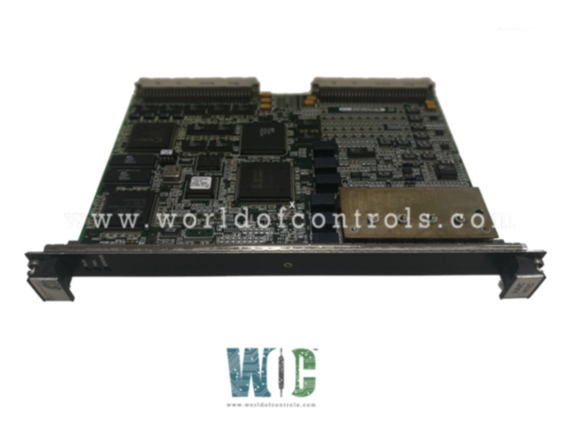
World Of Controls understands the criticality of your requirement and works towards reducing the lead time as much as possible.
IS200VAICH1CBA - Analog Input/Output (VAIC) Board is available in stock which ships the same day.
IS200VAICH1CBA - Analog Input/Output (VAIC) Board comes in UNUSED as well as REBUILT condition.
To avail our best deals for IS200VAICH1CBA - Analog Input/Output (VAIC) Board, contact us and we will get back to you within 24 hours.
SPECIFICATIONS:
Part Number: IS200VAICH1CBA
Manufacturer: General Electric
Series: Mark VI
Number of Channels: 24
Input Span: 4-20 mA
Input Impedance: 4-20 mA
Input Converter Resolution: 16-bit A/D Converter
Product Type: Analog Input/Output (VAIC) Board
Scan Time: 10 ms
Output Converter: 12-bit
Temperature Operating: 0 to 60°C
Memory: 128 MB of flash memory
Ethernet: 10BaseT/100BaseTX (RJ-45)
Microprocessor: Intel Celeron 300 MHz
Size: 26.04 cm high x 1.99 cm wide
Repair: 3-7 Day
Availability: In Stock
Weight: 2 lbs
Country of Origin: United States
Manual: GEH-6421M
FUNCTIONAL DESCRIPTION:
IS200VAICH1CBA is an Analog Input/Output (VAIC) Board Manufactured and designed by General Electric as part of the Mark VI Series used in GE Speedtronic Gas Turbine Control Systems. The Analog Input/Output (VAIC) board accepts 20 analog inputs and controls 4 analog outputs. Each terminal board accepts 10 inputs and 2 outputs. Cables connect the terminal board to the VME rack where the VAIC processor board is located. VAIC converts the inputs to digital values and transfers them over the VME backplane to the VCMI board, and then to the controller. For outputs, the VAIC converts digital values to analog currents and drives these through the terminal board into the customer circuit. VAIC supports both simplex and triple modular redundant (TMR) applications. When used in a TMR configuration, input signals on the terminal board are fanned out to three VME board racks R, S, and T, each containing a VAIC. Output signals are driven with a proprietary circuit that creates the desired current using all three VAICs. In the event of a hardware failure, the bad VAIC is removed from the output and the remaining two boards continue to produce the correct current. When used in a simplex configuration, the terminal board provides input signals to a single VAIC, which provides all of the current for outputs.
COMPATIBILITY:
There are two generations of the VAIC board with corresponding terminal boards. The original VAIC includes all versions before and including VAICH1C. VAICH1B is included in this generation. When driving 20 mA outputs these boards support up to 500 load resistance at the end of 1000 ft of 18 wire. This generation of the board requires terminal board TBAIH1B or earlier for proper operation. They also work properly with all revisions of DTAI terminal boards. The newest VAICH1D and any subsequent releases are designed to support higher load resistance for 20 mA outputs drive voltage: up to 18 V is available at the terminal board screw terminals. This permits operation into loads of 800 with 1000 ft of 18 wire with a margin. This generation of the board requires TBAIH1C or later, or any revision of STAI.
OPERATION:
There are two generations of the VAIC board with corresponding terminal boards. The original VAIC includes all versions before and including VAICH1C. VAICH1B is included in this generation. When driving 20 mA outputs these boards support up to 500 load resistance at the end of 1000 ft of 18 wire. This generation of the board requires terminal board TBAIH1B or earlier for proper operation. They also work properly with all revisions of DTAI terminal boards. The newest VAICH1D and any subsequent releases are designed to support higher load resistance for 20 mA outputs drive voltage: up to 18 V is available at the terminal board screw terminals. This permits operation into loads of 800 with 1000 ft of 18 wire with margin. This generation of the board requires TBAIH1C or later, or any revision of STAI.
WOC has the largest stock of OEM Replacement Parts for GE Speedtronic Gas Turbine Control Systems. We can also repair your faulty boards and supply unused and rebuilt boards backed up with a warranty. Our team of experts is available round the clock to support your OEM needs. Our team of experts at WOC is happy to assist you with any of your automation requirements. For pricing and availability on parts and repairs, kindly contact our team by phone or email.
What microprocessor is used in the board?
The board utilizes an Intel Celeron 300 MHz microprocessor, which manages processing tasks for handling analog signals and running the board’s software.
How can I determine if this board is compatible with my existing system?
The board is compatible with the original VAIC terminal boards (TBAIH1B or earlier) and all revisions of DTAI terminal boards. For newer systems, ensure compatibility with terminal boards TBAIH1C or later, or any revision of STAI.
What options are available for repairing this board?
WOC provides repair services for faulty boards, with a typical repair turnaround time of 3-7 days. They also offer unused and rebuilt boards with warranties.
How can I contact WOC for pricing and availability?
For pricing and availability, you can contact WOC’s team by phone or email. Their experts are available around the clock to assist with OEM parts and repairs.