World Of Controls understands the criticality of your requirement and works towards reducing the lead time as much as possible.
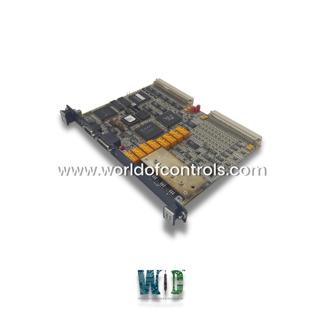
IS200VAICH1ACA - VME Analog Input/Output Board (VAIC) is available in stock which ships the same day.
IS200VAICH1ACA - VME Analog Input/Output Board (VAIC) comes in UNUSED as well as REBUILT condition.
To avail our best deals for IS200VAICH1ACA - VME Analog Input/Output Board (VAIC), contact us and we will get back to you within 24 hours.
TECHNICAL SPECIFICATIONS:
Part Number: IS200VAICH1ACA
Manufacturer: General Electric (GE)
Series: Speedtronic Mark VI
Functional Acronym: VAIC
Number of Channels: 24
Input Span: 4�20 mA
Product Type: VME Analog Input/Output Board
Hardware Revision: REV A (Functional Revision H1C, Artwork Revision A)
Redundancy Configuration: Supports Simplex and Triple Modular Redundant (TMR) systems
Analog Inputs: 20 channels (supporting 4�20 mA, �1 mA, �5 V DC, �10 V DC)
Analog Outputs: 4 channels (two 4�20 mA, two configurable for 4�20 mA or 0�200 mA)
Input Converter Resolution: 16-bit Analog-to-Digital (A/D) converter
Output Converter Resolution: 12-bit Digital-to-Analog (D/A) converter
Normal Operating Scan Time: 10 milliseconds (100 Hz frequency rate)
High-Speed Input Scan: Inputs 1 to 4 scan at a rapid 200 Hz frequency
Circuit Board Protection: High-grade conformal PCB coating
Ambient Operating Temperature: 0�C to +60�C (+32�F to +140�F) continuous range
Repair Lead Time: 3�5 business days
Availability: In Stock
Country of Origin: United States
Manual: GEH-6421M
The IS200VAICH1ACA is a VME Analog Input/Output Board (VAIC) designed and manufactured by General Electric for the Speedtronic Mark VI turbine control platform. The Analog Input/Output (VAICH1ACA) board accepts 20 analog inputs and controls 4 analog outputs. Each terminal board accepts 10 inputs and 2 outputs. Cables connect the terminal board to the VME rack, where the VAIC processor board is located. VAIC converts the inputs to digital values and transfers them over the VME backplane to the VCMI board, and then to the controller. For outputs, the VAIC converts digital values to analog currents and drives these through the terminal board into the customer circuit.
VAICH1ACA supports both simplex and triple modular redundant (TMR) applications. When used in a TMR configuration, input signals on the terminal board are fanned out to three VME board racks, R, S, and T, each containing a VAIC. Output signals are driven with a proprietary circuit that creates the desired current using all three VAICs. In the event of a hardware failure, the bad VAIC is removed from the output, and the remaining two boards continue to produce the correct current. When used in a simplex configuration, the terminal board provides input signals to a single VAIC, which provides all of the current for outputs.
COMPATIBILITY:
There are two generations of the VAIC board with corresponding terminal boards. The original VAIC includes all versions before and including VAICH1C. VAICH1B is included in this generation. When driving 20 mA outputs, these boards support up to 500 load resistance at the end of 1000 ft of #18 wire. This generation of board requires a terminal board TBAIH1B or earlier for proper operation. They also work properly with all revisions of the DTAI terminal boards. The newest VAICH1D and any subsequent releases are designed to support higher load resistance for 20 mA outputs. Drive voltage up to 18 V is available at the terminal board screw terminals. This permits operation into loads of 800 with 1000 ft of #18 wire with a margin. This generation of the board requires TBAIH1C or later, or any revision of STAI.
REDUNDANCY ARCHITECTURE & TRIPPING FAULT TOLERANCE
The VAIC card adapts seamlessly to either simplex or Triple Modular Redundant (TMR) system layouts. In high-reliability TMR control schemes, the analog inputs are split across three separate VME racks (R, S, and T panels), each fitted with an individual VAIC processor. A dedicated voting circuit coordinates the output signals; if an operational board anomaly occurs, the damaged card is structurally bypassed by integrated logic while the remaining operational boards continue to deliver uninterrupted current loops.
OPERATION:
The VAIC board accepts 20 analog inputs, controls 4 analog outputs, and contains signal conditioning, an analog MUX, an A/D converter, and a D/A converter. The type of analog input is either voltage, 4-20 mA, or terminal board. Two of the four analog output circuits are 4-20 mA, and the other two can be configured for 4-20 mA or 0-200 mA. Inputs and outputs have noise suppression circuitry to protect against surges and high-frequency noise.
In a TMR system, analog inputs fan out to the three control racks from JR1, JS1, and JT1. The 24 V dc power to the transducers comes from all three VME racks and is diode OR selected on the terminal board. Each analog current output is fed by currents from all three VAICs. The actual output current is measured with a series resistor, which feeds a voltage back to each VAIC. The resulting output is the voted middle value (median) of the three currents. The following figure shows VAIC in a TMR arrangement.
COMPRESSOR STALL DETECTION:
VAICH1ACA firmware includes gas turbine compressor stall detection, executed at 200 Hz. Two stall algorithms can be selected. Both use the first four analog inputs, scanned at 200 Hz. One algorithm is for small LM gas turbines and uses two pressure transducers (refer to the figure, Small (LM) Gas Turbine Compressor Stall Detection Algorithm). The other algorithm is for heavy-duty gas turbines and uses three pressure transducers (refer to the figure, Heavy Duty Gas Turbine Compressor Stall Detection Algorithm). Real-time inputs are separated from the configured parameters for clarity. The parameter CompStalType selects the type of algorithm required, either two transducers or three. PS3 is the compressor discharge pressure. A drop in this pressure (PS3 drop) indicates a possible compressor stall. The algorithm also calculates the rate of change of discharge pressure, dPS3dt, and compares these values with configured stall parameters (KPS3 constants). The compressor stall trip is initiated by VAIC, which sends the signal to the controller, where it is used to initiate a shutdown. The shutdown signal can be used to set all the fuel shut-off valves (FSOV) through any relay output.
WHY PARTNER WITH WORLD OF CONTROLS
World of Controls provides the industry's most dependable logistics and technical infrastructure for critical turbine control networks. We maintain an extensive inventory of genuine OEM replacement parts for GE Distributed control setups, minimizing operational downtime during emergency outages. Every item, from certified unused surplus to fully rebuilt industrial components, is subjected to strict simulation profiling in our advanced electronics lab and is supplied with a comprehensive product warranty. Our global engineering support network operates 24/7 to deliver troubleshooting advice, component replacement guidance, and component testing evaluations. Contact the WOC sales team directly via phone or email for current pricing, hardware availability, or repair quotes.
What is the GE IS200VAICH1ACA?
The GE IS200VAICH1ACA is a VME-based Analog Input/Output (VAIC) processor card designed for the Speedtronic Mark VI turbine control system. It acts as the centralized interface within the controller rack to process up to 20 continuous field transmitter inputs and manage 4 analog output command loops regulating modulating devices like valves or actuators.
What is the primary operational function of the GE IS200VAICH1ACA VME board?
The board serves as the core Analog Input/Output (VAIC) module within the Mark VI control system rack. It captures up to 20 analog signals from field transmitters, converts them into digital integers via an onboard 16-bit A/D converter, and channels up to 4 analog output currents back out to drive modulating equipment.
Why are two separate scanning frequencies applied across the input channels?
The board balances operational bandwidth by providing a standard 10 ms (100 Hz) scan interval for process signals, while reserving an accelerated 200 Hz high-speed sampling rate exclusively for inputs 1 through 4. This dual-rate tracking guarantees instantaneous acquisition for highly dynamic, time-critical inputs like gas turbine compressor stall markers.
How to configure the board to process different electrical signal scales?
Hardware configuration is modified using physical jumper pins located on the connected terminal boards (such as the TBAIH1C or STAI assemblies). By adjusting these jumper blocks, the channels can be matched to process standard 4-20 mA current loops, �1 mA signals, or absolute voltage ranges of �5 V DC and �10 V DC.
How to interpret diagnostic status messages using the faceplate assembly?
System health is verified by reading three diagnostic LEDs mounted on the front faceplate. A flashing green LED indicates standard software run status, a solid red indicates a critical board failure, and an orange status light alerts technicians to latched diagnostic warning anomalies in the controller software.
Why is a proprietary circuit utilized in TMR configuration modes?
In TMR configurations, the proprietary circuit links the outputs of three independent VAIC modules together to provide fault tolerance. If one card suffers a component failure or signal drift, its suicide relay detaches it from the output string, allowing the remaining two cards to maintain perfect control current without process bumps.