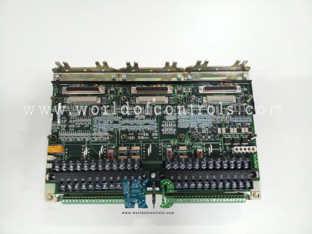
SPECIFICATIONS
Part Number: IS200TSVCH2ADC
Manufacturer: General Electric
Country of Manufacture: United States (USA)
Size: 33.02 cm high x 17.8 cm wide
Technology: Surface-mount
Temperature Operating: -30 to 65oC
Series: Mark VIe
Function: Servo Input/Output Terminal Board
Functional Description
IS200TSVCH2ADC is a servo input/output terminal board developed by GE. It is part of the GE Speedtronic Mark VIe gas turbine control system. The Servo Input/Output (TSVC) terminal board serves as a critical interface component within the control system, facilitating the control of two electro-hydraulic servo valves responsible for actuating the steam and fuel valves. These valves play a crucial role in regulating the flow of steam and fuel within the system, thereby controlling the overall operation and performance of the turbine-generator system.
Features
- Valve Position Measurement: The terminal board is equipped to interface with linear variable differential transformers (LVDT), which are used to measure the position of the valves accurately. This precise measurement ensures that the valves are operating within specified parameters, allowing for optimal control and regulation of steam and fuel flow.
- Compatibility and Design Considerations: Spoecifically designed to work in conjunction with the PSVO I/O pack and the WSVO servo driver. It is important to note that the TSVC terminal board is not compatible with the VSVO processor. This compatibility ensures seamless integration and efficient operation within the designated control system architecture.
- Support for Control Configurations: Supports various control configurations, including simplex, dual, and Triple Modular Redundancy (TMR) control setups. This flexibility allows operators to tailor the control system configuration to meet specific operational requirements and redundancy needs, ensuring reliability and resilience in critical applications.
- Power Supply and External Trip Integration: Three 28 V dc supplies are provided through plug J28, supplying power to the TSVC terminal board and associated components. Additionally, plugs JD1 or JD2 are designated for an external trip from the protection module, allowing for integration with external safety systems to ensure system integrity and safety.
Wiring Procedure
- Direct Wiring to I/O Terminal Blocks: Sensors and servo valves are wired directly to two I/O terminal blocks. Each terminal block is securely held down with two screws, providing stable connections.
- Terminal Block Specifications: Each terminal block features 24 terminals capable of accepting wiring up to #12 AWG. This ensures compatibility with various wiring configurations and sizes, accommodating the needs of different sensor and servo valve installations.
- Shield Terminal Strip: Adjacent to each terminal block, a shield terminal strip is attached to chassis ground. This grounding mechanism helps mitigate electromagnetic interference (EMI), ensuring the integrity of sensor and servo valve signals.
- External Trip Wiring: External trip wiring is plugged into either JD1 or JD2, allowing for integration with external safety systems. This ensures enhanced safety and system protection against fault conditions.
Servo Output Configuration
- Triple Modular Redundancy (TMR) Configuration: Each servo output can have three coils in a TMR configuration, providing redundancy and resilience in critical applications.
- Coil Current Selection: The size of each coil current is jumper-selected using JP1, JP3, and JP5 for Servo 1, and JP2, JP4, and JP6 for Servo 2. This configuration allows for precise control and optimization of servo valve operation.
Product Attributes
- Minimum Signal for Proper Measurement: For proper measurement at a frequency of 2 Hz, the minimum signal required is 33 mVpk (millivolts peak). Similarly, for a higher frequency of 12 kHz, the minimum signal required increases to 827 mVpk (millivolts peak). These signal thresholds ensure that the PR input can effectively detect and measure pulse rates across a wide range of operating conditions.
- Magnetic PR Pickup Signal: The magnetic PR pickup signal generates a peak-to-peak voltage of 150 V into a load impedance of 60 ohm. This signal is utilized for detecting rotational speed and position, providing crucial input for controlling the turbine-generator system.
- Active PR Pickup Signal: In contrast, the active PR pickup signal generates a variable peak-to-peak voltage ranging from 5 to 27 V into a load impedance of 60 ohm. This signal offers flexibility in signal amplitude and is often employed in applications where precise control and modulation of pulse rate inputs are required.
WOC has the largest stock of Speedtronic Mark VIe Spares and we can repair your faulty spares with a warranty. WORLD OF CONTROLS can also supply unused and rebuilt components backed by a warranty. Our team of experts is available round the clock to support your urgent needs related to critical spares, contact us.
FREQUENTLY ASKED QUESTIONS
What is IS200TSVCH2ADC?
It is a servo input/output terminal board and is part of the GE Speedtronic Mark VIe gas turbine control system.
How are diagnostic alarms managed?
Diagnostic alarms can be individually latched and reset. The RESETDIA signal resets alarms once issues are resolved.
How does the system handle hardware compatibility issues?
Each cable connector has an ID device. Mismatches trigger hardware incompatibility faults, ensuring proper connections.
How does the system handle unhealthy signals?
Unhealthy signals trigger a composite diagnostic alarm (LDIAG_PSVO), indicating potential issues requiring attention.
