World Of Controls understands the criticality of your requirement and works towards reducing the lead time as much as possible.
IS200TRTDH1BBB - RTD Input Terminal Board is available in stock which ships the same day.
IS200TRTDH1BBB - RTD Input Terminal Board comes in UNUSED as well as REBUILT condition.
To avail our best deals for IS200TRTDH1BBB - RTD Input Terminal Board, contact us and we will get back to you within 24 hours.
SPECIFICATIONS:
Part Number: IS200TRTDH1BBB
Manufacturer: General Electric
Series: Mark VIe
Product Type: RTD Input Terminal Board
Thermocouple types: E, J, K, S, T thermocouples
Number of channels: 24 channels
Number of Outputs: 2
Frequency: 3.2 ±0.2 kHz
Span: -8 mV to +45 mV
Power supply current: 5 A dc
Mounting: DIN-rail mounting
Technology: Surface mount
Measurement accuracy: 53 mV
Maximum Distance: 300 m
Operating temperature: -30° to 65°C
Size: 33.02 cm high x 17.8 cm wide
Repair: 3-7 Days
Availability: In Stock
Country of Origin: United States
Manual: GEH-6721G
FUNCTIONAL DESCRIPTION:
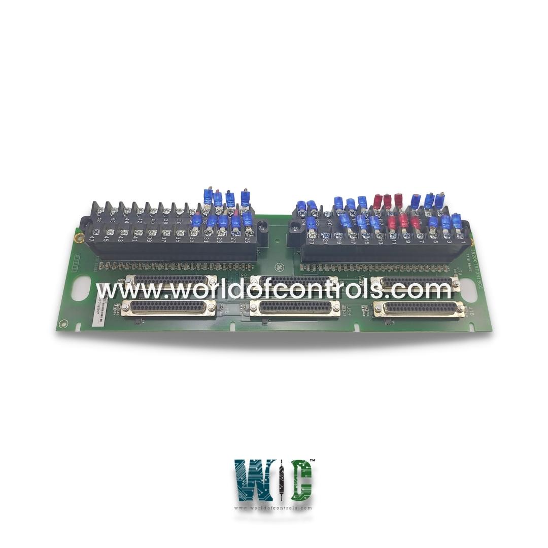
IS200TRTDH1BBB is an RTD Input Terminal Board manufactured and designed by General Electric as part of the Mark VIe Series used in GE Distributed Turbine Control Systems. The RTD Input (TRTD) terminal board accepts 16, three-wire RTD inputs. These inputs are wired to two barrier-type terminal blocks. The inputs have noise suppression circuitry to protect against surges and high-frequency noise. TRTD communicates with one or more I/O processors, which convert the inputs to digital temperature values and transfer them to the controller. There are four versions of TRTD as follows:
INSTALLATION:
Connect the wires for the 16 RTDs directly to the two terminal blocks on the terminal board. Each block is held down with two screws and has 24 terminals accepting up to #12 AWG wires. A shield terminal strip attached to chassis ground is located immediately to the left of each terminal block. In a TMR Mark VI control system, TRTDH1B provides redundant RTD inputs by fanning the inputs to three VRTD boards in the R, S, and T racks. The inputs meet the same environmental, resolution, suppression, and function requirements and codes as the TRTDH1C terminal board; however, the fast scan is not available.
OPERATION:
TRTD supplies a 10 mA dc multiplexed (not continuous) excitation current to each RTD, which can be grounded or ungrounded. The 16 RTDs can be located up to 300 m (984 ft) from the turbine control cabinet with a maximum two-way cable resistance of 15 Ω. The A/D converter in the I/O processor samples each signal and the excitation current four times per second for normal mode scanning and 25 times per second for fast mode scanning, using a time sample interval related to the power system frequency. Software performs the linearization for the selection of 15 RTD types. RTD open and short circuits are detected by out-of-range values.
An RTD that is determined to be outside the hardware limits is removed from the scanned inputs to prevent adverse effects on other input channels. Repaired channels are reinstated automatically in 20 seconds or can be manually reinstated. All RTD signals have high-frequency decoupling to ground at signal entry. RTD multiplexing in the I/O processor is coordinated by redundant pacemakers so that the loss of a single cable or I/O processor does not cause the loss of any RTD signals in the control database.
DIAGNOSTICS:
Each RTD type has hardware limit checking based on preset (non-configurable) high and low levels set near the ends of the operating range. If this limit is exceeded, a logic signal is set, and the input is no longer scanned. If any one of the input’s hardware limits is set, it creates a composite diagnostic alarm, L3DIAG_xxxx, referring to the entire board. Details of the individual diagnostics are available from the toolbox. The diagnostic signals can be individually latched and then reset with the RESET_DIA signal.
WOC is proud to offer the largest stock of OEM replacement parts for GE Distributed Turbine Control Systems, ensuring you have access to the critical components you need for maintenance, upgrades, or replacements. In addition to supplying genuine parts, we specialize in repairing faulty boards and providing unused and professionally rebuilt boards, all supported by a reliable warranty to guarantee performance and peace of mind. Our team of experts is available round the clock to offer technical guidance and solutions tailored to your automation and control system requirements. Committed to maximizing uptime and operational efficiency, we are always ready to assist with any OEM needs, from parts procurement to repairs. For pricing, availability, or support, please contact our team via phone or email at WOC. Your automation challenges are our top priority, and we are dedicated to delivering fast, reliable, and expert solutions.
What is the IS200TRTDH1BBB?
The IS200TRTDH1BBB is an RTD Input Terminal Board designed for GE’s Mark VIe Distributed Turbine Control Systems. It supports 16 three-wire RTD inputs and interfaces with I/O processors for temperature signal conversion. Built-in noise suppression circuitry ensures stable and reliable measurement performance in industrial environments.
What types of sensors are supported by this terminal board?
The board is designed specifically for RTDs but also supports systems using thermocouple types E, J, K, S, and T. The RTDs can be grounded or ungrounded, offering flexibility in field installations. It provides accurate digital temperature readings through the connected I/O processors.
How many RTDs can be connected to the IS200TRTDH1BBB?
This board supports up to 16 three-wire RTD inputs. The RTDs are connected through two barrier-type terminal blocks, each offering secure screw terminals. Proper wiring ensures accurate temperature sensing and reliable communication with the I/O processors.