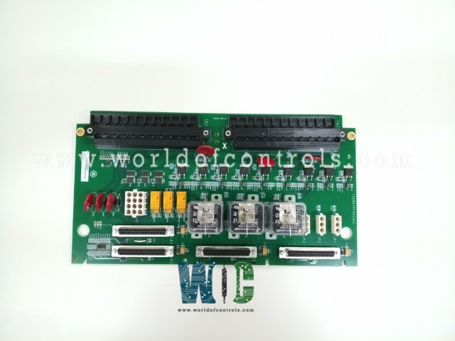
SPECIFICATIONS
Part No.: IS200TRPSH1ACC
Manufacturer: General Electric
Country of Manufacture: United States of America (USA)
Temperature Operating: -30 to 65 o C
Current suppression: MOVs
Product Type: Trip Output Terminal Board
Availability: In Stock
Series: Mark VIe
Functional Description
IS200TRPSH1ACC is a trip output terminal board developed by GE. It is a part of Mark VIe control system. The TRPS terminal board plays a pivotal role in providing primary overspeed protection for small and medium-sized steam turbines. It operates under the control of the turbine I/O controller and facilitates the interface with three trip solenoids, termed Electrical Trip Devices (ETD).
Functionality and Interface
- Control and Interface: TRPS integrates three magnetic relays specifically designed to interface with the three trip solenoids (ETDs). It collaborates with the TRES terminal board to establish the primary and emergency sides of the interface to these ETDs. This collaboration ensures effective overspeed protection mechanisms.
- Comparison with Gas Turbine Applications: While TRPS and TRES function similarly to TRPG and TREG in gas turbine applications, several key differences exist:
- Voting Mechanism: Instead of relay contacts, two-out-of-three voting occurs within the relay drivers themselves.
- Simplex Application Control: In a simplex setup, the voting process is bypassed, and relay drivers are controlled by a single signal from JA1, streamlining the operation.
- Exclusion of Certain Features: TRPS lacks economizing relays and flame detector inputs, differing from their inclusion in gas turbine applications.
Trip Solenoid Connections and Emergency Stop Functions
- Solenoid Connections: Up to three trip solenoids can be connected between the TRES and TRPS terminal boards. TRES supplies the positive side of the 125 V dc to the solenoids, while TRPS provides the negative side, ensuring effective power distribution for solenoid operation.
- Emergency Stop Functionality: Additionally, provision is made for wiring two manual emergency stop functions, enhancing safety protocols for immediate shutdowns in emergency situations.
Features
- Interface with ETDs: Integration with three magnetic relays to interface with trip solenoids (ETDs).
- Differences from Gas Turbine Applications: Relay driver-based voting, simplex application control, absence of economizing relays, and flame detector inputs.
- Solenoid Connections: Power provision for trip solenoids via TRES and TRPS terminal boards.
- Emergency Stop Provision: Wiring provisions for two manual emergency stop functions for added safety.TRPS terminal board is crucial for primary overspeed protection in small and medium-sized steam turbines. Its functionalities, relay-based control mechanisms, interface provisions for trip solenoids, and emergency stop capabilities collectively ensure a robust and reliable overspeed protection system for these turbines.
Terminal Installation
- The trip solenoids, crucial components for overspeed protection, are connected to the first I/O terminal block. This block serves as the central point for wiring these solenoids, allowing their seamless integration into the TRPS terminal board system. Simultaneously, the second terminal block is dedicated to managing the wiring connections for both the primary emergency stop and, optionally, a secondary emergency stop mechanism.
- To ensure proper functionality, the power supply for the trip solenoids is channeled through designated plugs, specifically labeled as JP1, JP2, and JP3. These plugs serve as the power distribution points, supplying the necessary power to operate the trip solenoids effectively.
- In scenarios requiring an additional layer of safety measures, an optional secondary emergency stop can be implemented. Wiring to terminals 46 and 47 facilitates the integration of this secondary emergency stop mechanism. Additionally, to activate this secondary function, it's essential to remove the jumper associated with the setup.
- Terminal Block Allocation: The first block is dedicated to trip solenoid wiring, while the second block manages primary and optional secondary emergency stop functions.
Power Distribution: Plugs JP1, JP2, and JP3 serve as designated points for distributing power to the trip solenoids, ensuring their efficient operation.
Secondary Emergency Stop Configuration: Wiring connections to terminals 46 and 47 enable the integration of an optional secondary emergency stop function, requiring the removal of a specific jumper for activation.
The WOC team is always available to help you with your Mark VIe requirements. For more information, please contact WOC.
Frequently Asked Questions
What is IS200TRPSH1ACC?
It is a trip output terminal board developed by GE under the Mark VIe series.
What diagnostics does the I/O controller perform on the terminal board?
The I/O controller runs diagnostics encompassing trip solenoid relay drivers, solenoid voltage, power bus, and trip solenoid relay contacts. These diagnostics monitor the health and functionality of critical components.
How does the system indicate potential issues in the board?
Any deviation or unhealthy state in monitored signals triggers a diagnostic alarm. This alarm promptly alerts operators to potential issues or discrepancies within the monitored components.
What role do ID devices play on connectors J00, JR1, JS1, and JT1?
Each connector includes an ID device interrogated by the I/O board. If there's a mismatch in the identified ID information, the system generates a hardware incompatibility fault. This fault serves as an indicator of potential hardware compatibility issues within the system.
