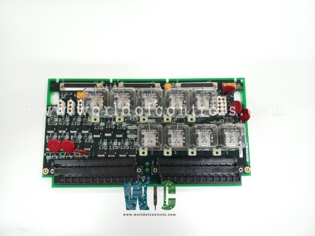
SPECIFICATIONS
Part No.: IS200TRPLH1ABB
Manufacturer: General Electric
Country of Manufacture: United States of America (USA)
Current suppression: MOVs
Temperature: -30 to 65oC
Trip solenoids: 3
Humidity: 5 to 95 percent non-condensing
Primary Emergency Stop, manual: One with optional secondary E-stop
Product Type: Turbine Primary Trip Terminal Board
Availability: In Stock
Series: Mark VIe
Functional Description
IS200TRPLH1ABB is a Turbine Primary Trip Terminal Board developed by GE. It is part of Mark VIe control system. It serves as the primary interface for overspeed protection in large steam turbines. It is controlled by the turbine's Primary Turbine Protection controller (VTUR or PTUR), providing essential safety measures to prevent turbine overspeed incidents.
Features
- Relay Configuration: The terminal board comprises nine magnetic relays organized into three voting circuits. These relays are designed to interface with three trip solenoids (ETDs), facilitating rapid and precise responses to potential overspeed conditions.
- Collaboration with TREL Terminal Board: Collaborates closely with the TREL terminal board to establish the primary and emergency sides of the interface to the ETDs. Similar to the setup in gas turbine applications with TRPG and TREG terminal boards, this arrangement ensures comprehensive overspeed protection.
- Trip Solenoid Connectivity: Up to three trip solenoids can be connected between the TREL and terminal boards. TREL provides the positive side of the 125 V DC power supply to the solenoids, while it supplies the negative side. This configuration ensures reliable and efficient operation of the trip solenoids.
- Emergency Stop Functionality: In addition to overspeed protection, TRPL supports two manual emergency stop functions. These functions provide an additional layer of safety, allowing operators to halt turbine operation swiftly in emergency situations.
Installation
- Trip Solenoid Wiring: Connect the wires for the three trip solenoids directly to the first I/O terminal block on the TRPL terminal board. Ensure secure and proper connections to facilitate reliable operation during overspeed conditions.
- Emergency Stop Wiring: Wire the primary emergency stop and, if applicable, the optional secondary emergency stop to the second terminal block on the terminal board. Confirm the connections are correctly established to enable prompt response during emergency situations.
- Trip Solenoid Power Connection: Connect the trip solenoid power to plugs JP1, JP2, and JP3 on the TRPL terminal board. Ensure the power connections are secure and properly insulated to prevent any electrical hazards.
- Jumper Installation for PTR3 Trip: Install a jumper across terminals 9 and 11 on the terminal board specifically for the PTR3 trip. This jumper ensures the proper functioning of the overspeed protection system and should be securely in place.
- Optional Secondary Emergency Stop Configuration: If a second emergency stop is required, remove the jumper from terminals 46 and 47 on the TRPL terminal board. Connect the wires for the secondary emergency stop to these terminals, following the provided wiring diagram.
- Verification: Double-check all wiring connections and jumper installations to ensure they align with the provided instructions and wiring diagrams. Verify that all connections are secure and properly insulated to prevent any electrical issues.
Configuration
- Jumper Installation for PTR3 Trip: To activate the PTR3 trip functionality, install a jumper across terminals 9 and 11 on the TRPL terminal board. This jumper is essential for including the PTR3 trip in the overspeed protection system. Ensure the jumper is securely in place to enable the proper functioning of the trip circuit.
- Jumper Installation for Manual Emergency Stop: If only one manual emergency stop is required, install a jumper across terminals 46 and 47 on the TRPL terminal board. This jumper configuration ensures that the primary emergency stop functionality is activated. Verify that the jumper is correctly installed to facilitate emergency shutdown capability as needed.
- No Hardware Settings or Switches: Unlike some terminal boards, the TRPL terminal board does not feature switches or hardware settings for configuration. All configuration adjustments are made using jumpers across specific terminals. This simplifies the configuration process and ensures consistency in setup across installations.
- Verification of Jumper Installations: After installing the jumpers for PTR3 trip and manual emergency stop, verify their installations to confirm proper configuration. Ensure that the jumpers are securely in place and make necessary adjustments if any discrepancies are found.
The WOC team is always available to help you with your Mark VIe requirements. For more information, please contact WOC.
Frequently Asked Questions
What is IS200TRPLH1ABB?
It is a Turbine Primary Trip Terminal Board developed by GE under the Mark VIe series.
Are there any hardware settings or switches for configuring the terminal board?
No, the board does not feature any hardware settings or switches for configuration. All configuration adjustments are made using jumpers across specific terminals, as outlined in the provided guidelines.
How do I activate the PTR3 trip functionality on the TRPL board?
To activate the PTR3 trip, you must install a jumper across terminals 9 and 11 on the TRPL terminal board. This jumper is necessary to include the PTR3 trip in the overspeed protection system.
What is the purpose of installing a jumper across terminals 46 and 47 on the terminal board?
Installing a jumper across terminals 46 and 47 is required if only one manual emergency stop is needed. This configuration ensures that the primary emergency stop functionality is activated on the terminal board.
