SPECIFICATIONS
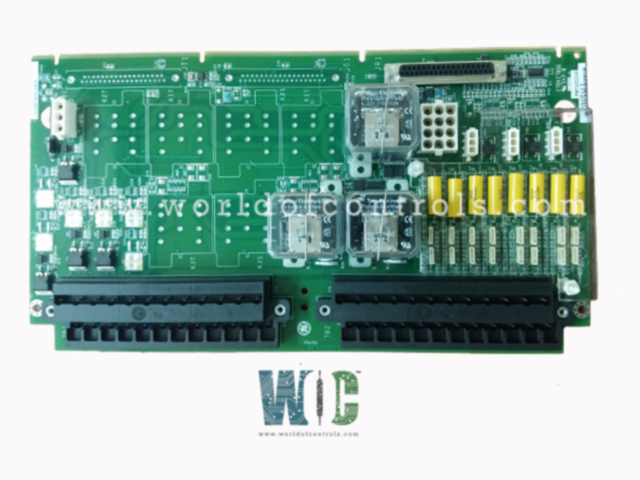
Part No.: IS200TRPGH2BDD
Manufacturer: General Electric
Country of Manufacture: United States of America (USA)
Temperature: 0 to 60 °C
Size: 26.04 cm high x 1.99 cm wide x 18.73 cm deep
Power consumption: Less than 31 MW
Compressor stall detection: Detection and relay operation within 30 ms
Product Type: Primary Gas Turbine Trip Output Board
Availability: In Stock
Series: Mark VI
Functional Description
IS200TRPGH2BDD is a Primary Gas Turbine Trip Output Board developed by GE. It is a part of Mark VI control system. Controlled by the I/O controller, the TRPG is designed to interface with Electrical Trip Devices (ETD) through magnetic relays, ensuring the reliability and safety of the system.
Interface with Electrical Trip Devices (ETD)
- The TRPG incorporates nine magnetic relays organized into three voting circuits, each interfacing with a dedicated trip solenoid.
- These trip solenoids, collectively known as Electrical Trip Devices (ETD), are integral components in initiating trips or shutdowns when specific conditions or faults are detected in the system. The three voting circuits provide redundancy, enhancing the reliability of the trip initiation process.
Collaboration with TREG
- To form a robust interface with the ETDs, the TRPG collaborates with the TREG.
- The combined functionality of TRPG and TREG ensures the establishment of both primary and emergency sides of the interface to the ETDs.
- This dual-sided approach adds an extra layer of reliability to the trip initiation system, allowing for effective and swift response to critical situations.
Flame Detection Capability
- In addition to its primary role in trip initiation, the TRPG is equipped to handle inputs from eight Geiger Mueller flame detectors in gas turbine applications.
- This flame detection capability enhances the safety features of the system by providing real-time monitoring for the presence or absence of flames within the turbine environment. Rapid and accurate flame detection is crucial for preventing potential hazards and ensuring the safe operation of the gas turbine.
Compatibility
- The H2A version of the TRPG is designed for simplex applications, featuring a configuration where each trip solenoid is associated with one relay. This streamlined setup is suitable for scenarios where redundancy is not a critical requirement, providing a cost-effective solution for applications with straightforward operational demands.
Installation
- Trip Solenoids Connection: The three trip solenoids, critical components for initiating shutdowns, are directly wired to the first I/O terminal block. This ensures a direct and secure connection between the TRPG and the trip solenoids, minimizing potential points of failure and optimizing the reliability of the system.
- Flame Detectors Integration: In systems incorporating flame detectors, these devices are connected to the second terminal block. The wiring for flame detectors, if used, is meticulously organized to provide a reliable interface with the terminal board. This step is essential for enabling real-time flame detection capabilities in gas turbine applications.
- Power Supply for Flame Detectors: The power supply for the flame detectors is facilitated through dedicated wiring to connectors J3, J4, and J5. This ensures a stable and independent power source for the flame detection system, enhancing the overall safety and reliability of the installation.
- Power Distribution: The terminal board manages power distribution for critical components in the system. Specifically, the 125 V DC power required for the operation of the trip solenoids is routed through connector J1. This dedicated power connection is vital for the proper functioning of the trip solenoids, enabling them to respond promptly to potential faults or critical conditions.
- Board Power Transfer: Connector J2 facilitates the transfer of power to the board. This ensures that the TREG, working in conjunction with the TRPG, receives the necessary power supply for its operation. The coordination between these two boards is essential for maintaining a reliable interface to the Electrical Trip Devices (ETD) and responding effectively to system contingencies.
- Compliance and Safety Measures: During the installation process, it is imperative to adhere to industry standards and guidelines to guarantee the safety and compliance of the entire system. All wiring connections should be secured and verified, and power distribution must align with the specified voltage requirements for each component. Regular testing and verification procedures should be implemented post-installation to confirm the integrity of the connections and the proper functioning of the TRPG terminal board in conjunction with associated components.
The WOC team is always available to help you with your Mark VI requirements. For more information, please contact WOC.
Frequently Asked Questions
What is IS200TRPGH2BDD?
It is a Primary Gas Turbine Trip Output Board developed by GE under the Mark VI series.
What is the primary function of the I/O board in the system?
The I/O board serves as the primary controller for the trip function by managing the relays on the TRPG (Trip Relay and Power Supply) board. These relays play a crucial role in tripping the main protection solenoids, initiating shutdowns when necessary.
How does the I/O board operate in Triple Modular Redundant applications?
In TMR applications, the I/O board employs a hardware-based voting mechanism using a relay ladder logic two-out-of-three voting circuit. This ensures redundancy and reliability in decision-making processes, enhancing the overall robustness of the system.
How does the I/O board determine the vote/status of the relay coil contacts in TMR applications?
The I/O board monitors the current flow in its relay driver control line to ascertain the energize or de-energize vote/status of the relay coil contacts. This meticulous monitoring allows the I/O board to make informed decisions based on the health and status of the relay components.
What diagnostic measures are implemented by the I/O board for monitoring purposes?
The I/O board incorporates diagnostic measures to monitor the current flow in its relay driver control line and to check the supply voltages. These diagnostic functionalities serve to ensure the proper functioning and health of the components, contributing to the overall reliability of the system.
