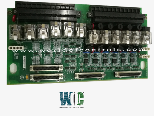
IS200TRLYH1BGE - Relay Output Board

IS200TRLYH1BGE - Relay Output Board IS200TRLYH1BGE - Relay Output Board

World Of Controls understands the criticality of your requirement and works towards reducing the lead time as much as possible.

IS200TRLYH1BGE - Relay Output Board is available in stock which ships the same day.

IS200TRLYH1BGE - Relay Output Board comes in UNUSED as well as REBUILT condition.

To avail our best deals for IS200TRLYH1BGE - Relay Output Board, contact us and we will get back to you within 24 hours.

SPECIFICATIONS

Part No.: IS200TRLYH1BGE
Manufacturer: General Electric
Country of Manufacture: United States of America (USA)
Max response time on: 25 ms typical
Max response time off: 25 ms typical
Contact material: Silver cad-oxide
Temperature Operating: -30 to 65oC
Product Type: Relay Output Board
Availability: In Stock
Series: Mark VIe

Functional Description

IS200TRLYH1BGE is a Relay Output Board developed by GE. It is a part of the Mark VIe control system. The terminal board is designed to accommodate 12 plug-in magnetic relays and offers various configuration options. The first six relay circuits on the board can be configured using jumpers. Users have the option to set them for dry contacts, Form-C contact outputs, or to drive external solenoids.

Features

  • Power Source Options: The board supports different power sources for the relay circuits. Users can choose between a standard 125 V DC, 115/230 V AC source, or an optional 24 V DC source. Each relay circuit features individual jumper-selectable fuses and on-board suppression for field solenoid power, ensuring flexibility and protection.
  • Relay Functionality: Relays 7 to 11 on the board are unpowered, isolated Form-C contacts. These contacts provide versatile functionality for various applications where power isolation is required.
  • Special Application Relay: Output 12 on the board is an isolated Form-C contact designed for special applications, such as for ignition transformers. This dedicated relay offers specific functionality tailored to unique system requirements.

Installation

  • Mounting the Terminal Blocks: The 12 relay outputs are directly wired to two I/O terminal blocks positioned on the terminal board. Each block is securely fastened using two screws and features 24 terminals capable of accepting up to 12 AWG wires.
  • Grounding: Adjacent to each terminal block, a shield terminal strip is attached to chassis ground. This grounding mechanism helps mitigate electromagnetic interference (EMI) and ensures proper grounding of the system.
  • Solenoid Power Connection: For outputs 1 to 6, solenoid power is typically connected to connector JF1. Connector JF2 can be utilized to daisy chain power to other TRLYH1B terminal boards if needed. Alternatively, customers have the option to directly wire power into TB3 when not using connectors JF1/JF2.
  • Special Solenoid Power: Output 12 requires power for the customer's special solenoid. This power is provided through connector JG1, which is dedicated to supplying power for this specific output.

Configuration

  • Jumpers (JP1 through JP12): Jumpers are provided for each relay circuit to accommodate specific requirements, particularly for contact voltage sensing. When contact voltage sensing is necessary, jumpers should be inserted for the selected relays accordingly. These jumpers facilitate the proper operation of the relays based on the desired voltage sensing configurations.
  • Fuses (FU1 through FU12): The terminal board features fuse slots corresponding to each relay circuit. For relays 1 to 6, where power supply is required, two fuses should be placed in each power circuit supplying these relays. Proper placement of fuses ensures the appropriate protection and distribution of power to the respective relay circuits, enhancing the reliability and safety of the system.

The WOC team is always available to help you with your Mark VIe requirements. For more information, please contact WOC.

Frequently Asked Questions

What is IS200TRLYH1BGE?
It is a Relay Output Board developed by GE under the Mark VIe series.

What adjustments are available on the board?
The terminal board offers adjustments primarily through jumpers and fuses.

How are jumpers utilized on the board?
Jumpers, labeled JP1 through JP12, are used to configure specific relay circuits, particularly for contact voltage sensing. When contact voltage sensing is required, jumpers should be inserted for the selected relays accordingly.

What is the purpose of fuses on the board?
Fuses, labeled FU1 through FU12, provide protection and distribution of power to the relay circuits. For relays 1 to 6, where power supply is necessary, two fuses should be placed in each power circuit supplying these relays.

How do these adjustments contribute to system operation?
Proper adjustment of jumpers and the installation of fuses ensure the reliable and safe operation of the terminal board within the system. These adjustments allow users to customize the board configuration based on specific operational requirements, enhancing overall functionality and performance.