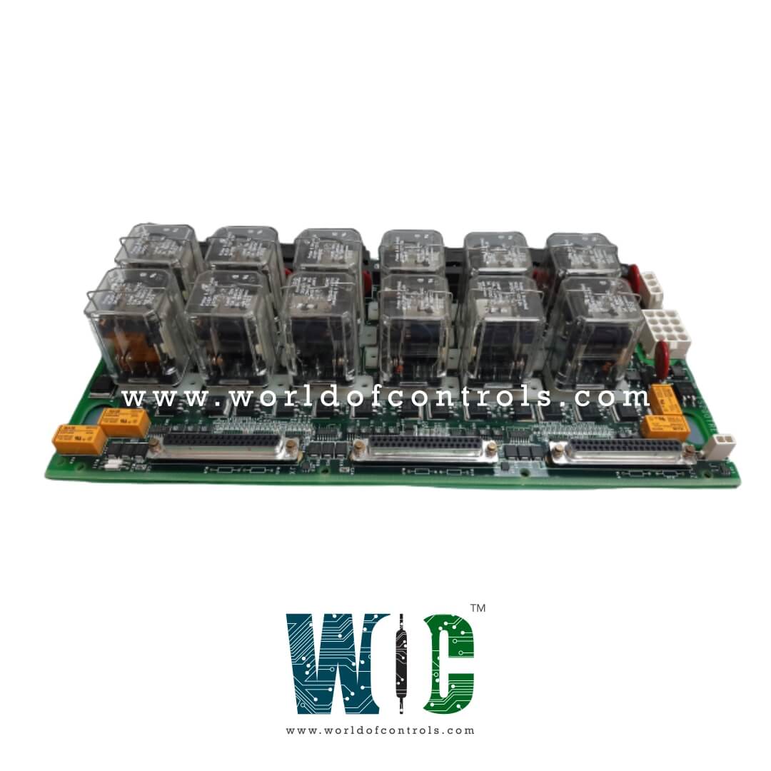
World Of Controls understands the criticality of your requirement and works towards reducing the lead time as much as possible.
IS200TREGH3B - Turbine Emergency Trip Terminal Board is available in stock which ships the same day.
IS200TREGH3B - Turbine Emergency Trip Terminal Board comes in UNUSED as well as REBUILT condition.
To avail our best deals for IS200TREGH3B - Turbine Emergency Trip Terminal Board, contact us and we will get back to you within 24 hours.
TECHNICAL SPECIFICATIONS:
Part Number: IS200TREGH3B
Manufacturer: General Electric
Series: Mark VI
Functional Acronym: TREG
Number of trip Solenoids: 3
Trip Solenoid Rating: H1 -125 V dc
Product Type: Turbine Emergency Trip Terminal Board
Number of Trip Solenoids: Supports up to 3 emergency trip solenoids
Trip Solenoid / Contact Rating: 125 V DC nominal
Power Source Configuration: JX1 connector
Ambient Operating Temperature: -30 °C to +65 °C
Mounting Design: Surface-mount technology / DIN-rail mounting
Repair / Evaluation Lead Time: 3-7 Business Days
Trip Interlock Filter: 4 ms
Trip Interlock Ac Voltage: 60 V rms
Size: 17.8 cm x 33.02 cm
Availability: In Stock
Country of Origin: United States
Manual Reference: GEH-6421I
The IS200TREGH3B is a Turbine Emergency Trip Terminal Board designed and manufactured by General Electric for its primary Speedtronic turbine protection and control systems. TREGH3B provides power to three emergency trip solenoids and is controlled by the I/O controller. Up to three trip solenoids can be connected between the TREG and TRPG terminal boards. TREG provides the positive side of the de power to the solenoids, and TRPG provides the negative side. The I/O controller provides emergency overspeed protection, emergency stop functions, and controls the 12 relays on TREG, nine of which form three groups of three to vote inputs controlling the three trip solenoids. There are several board types as follows:
The HIA version is not used for new production and is replaced by HIB.
CONTROL OF TRIP SOLENOIDS:
A separately fused 125 V dc feeder is provided from the turbine control for the solenoids, which energize in the run mode and de-energize in the trip mode. Diagnostics monitor each 125 V dc feeder from the power distribution module at its point of entry on the terminal board to verify the fuse integrity and the cable connection. Two series contacts from each emergency trip relay (ETR1, 2, 3) are connected to the positive 125 V dc feeder for each solenoid, and two series contacts from each primary trip relay (PTR1,2,3 in TRPG) are connected to the negative 125 V dc feeder for each solenoid. An economizing relay (KE1, 2, 3) is supplied for each solenoid with a normally closed contact in parallel with the current-limiting resistor. These relays are used to reduce the current load after the solenoids are energized.
The ETR and KE relay coils are powered from a 28 V DC source from the I/O controller. Each PPRÓ I/O pack in each of the R8, S8, and T8 sections supplies an independent 28 V dc source. The 28 V dc bus is current-limited and used for power to an external manual emergency trip contact, shown as E-STOP. Three master trip relays (K4X, K4Y, K4Z) disconnect the 28 V dc bus from the ETR and KE relay coils if a manual emergency trip occurs. Any trip that originates in either the protection module (such as EOS) or the TREG (such as a manual trip) will cause each of the three protection module sections to transmit a trip command over the IONet to the control module, and may be used to identify the source of the trip.
CONTROL OF TRIP SOLENOIDS:
Both TRPG and TREG control the trip solenoids so that either one can remove power and actuate the hydraulics to close the steam or fuel valves. The nine trip relay coils on TREG are supplied with 28 V dc from the I/O controller. The trip solenoids are supplied with 125 V dc through plug J2, and draw up to 1 A with a 0.1 second L/R time constant.
A separately fused 125 V dc feeder is provided from the turbine control for the solenoids, which energize in the run mode and de-energize in the trip mode. Diagnostics monitor each 125 V dc feeder from the power distribution module at its point of entry on the terminal board to verify the fuse integrity and the cable connection.
Two series contacts from each emergency trip relay (ETR1, 2, 3) are connected to the positive 125 V dc feeder for each solenoid, and two series contacts from each primary trip relay (PTR1,2,3 in TRPG) are connected to the negative 125 V dc feeder for each solenoid. An economizing relay (KE1, 2, 3) is supplied for each solenoid with a normally closed contact in parallel with the current-limiting resistor. These relays are used to reduce the current load after the solenoids are energized. The ETR and KE relay coils are powered from a 28 V dc source from the I/O controller. Each PPRO I/O pack in each of the R8, S8, and T8 sections supplies an independent 28 V dc source.
The 28 V dc bus is current limited and used for power to an external manual emergency trip contact, shown as E-STOP. Three master trip relays (K4X, K4Y, K4Z) disconnect the 28 V dc bus from the ETR, and KE relay coils if a manual emergency trip occurs. Any trip that originates in either the protection module (such as EOS) or the TREG (such as a manual trip) will cause each of the three protection module sections to transmit a trip command over the IONet to the control module, and may be used to identify the source of the trip.
WHY PARTNER WITH WORLD OF CONTROLS
World of Controls specializes in supplying high-quality, warranty-backed OEM replacement parts, including unused surplus and professionally rebuilt components, for critical turbine control and industrial automation systems like the General Electric Mark VI and Mark VIe platforms. To minimize customer downtime and ensure original equipment standard compliance, every component undergoes rigorous inspection, testing, and verification in an advanced electronics lab. Beyond parts distribution, the company delivers comprehensive, global support through 24/7 technical assistance, expert troubleshooting, component repair services, and rapid shipping, ensuring optimal efficiency and long-term reliability for critical industrial operations worldwide.
What is GE IS200TREGH3B?
It is a high-reliability Gas Turbine Emergency Trip Terminal Board (TREG) manufactured by General Electric for the Speedtronic Mark VI and Mark VIe series. It interfaces protection I/O controllers with emergency trip solenoids to safely shut down the turbine when fault limits are breached.
What can cause a trip solenoid circuit to remain de-energized?
Possible causes include a blown feeder fuse, an open cable connection, loss of the 125 V DC supply, defective relay contacts, or a problem elsewhere in the associated protection circuitry. The Mark VI diagnostics monitor the feeder at the terminal board to help identify fuse and connection issues. Wiring, supply voltage, relay operation, and associated TRPG circuitry should be checked before replacing the board.
What should be checked if the board reports a trip circuit fault?
Start by checking the 125 V DC feeder, associated fuses, field wiring, connector seating, and relay operation. The 28 V DC supply used for the TREG relay coils should also be verified. If the external circuits are functioning correctly, the board can be evaluated for relay, feedback, or other circuit-level faults.
What could cause incorrect trip status feedback?
Incorrect feedback may result from a loss of auxiliary power, wiring problems, connector issues, relay contact faults, or a failure in the feedback circuitry. For the H3B configuration, the JX1 power connection is particularly important because it supplies the feedback and economizing relay circuits. Diagnostic indications should be compared with measured supply voltages and field conditions.
What is the function of the JX1 connector?
For the H3B configuration, the JX1 connector provides power for the feedback circuitry and economizing relays. Unlike the standard H1B configuration, the H3B version is intended for systems using redundant TREG boards and receives this auxiliary power through JX1. The trip relay circuits maintain their required power separation.
How does the board control the emergency trip circuit?
The board uses emergency trip relays to control the positive side of the 125 V DC supply to the trip solenoids. The corresponding TRPG circuitry controls the negative side, allowing either board to remove power and initiate the turbine trip action. The arrangement provides redundant control of the hydraulic valve-closing function.