World Of Controls understands the criticality of your requirement and works towards reducing the lead time as much as possible.
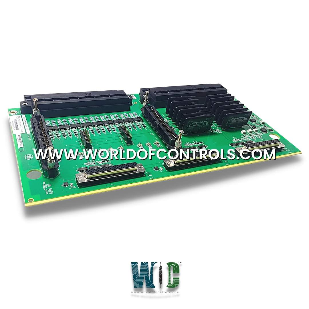
IS200TREAH3A - Aeroderivative Turbine Emergency Trip Terminal Board is available in stock which ships the same day.
IS200TREAH3A - Aeroderivative Turbine Emergency Trip Terminal Board comes in UNUSED as well as REBUILT condition.
To avail our best deals for IS200TREAH3A - Aeroderivative Turbine Emergency Trip Terminal Board, contact us and we will get back to you within 24 hours.
SPECIFICATIONS:
Part Number: IS200TREAH3A
Manufacturer: General Electric
Series: Mark VIe
Product Type: Aeroderivative Turbine Emergency Trip Terminal Board
Number of channels: 24
Number of Inputs: 9
Span: -8 mV to +45 mV
Power supply voltage: 28 V DC
Voltage Range: 18 - 32 VDC
Mounting: DIN-rail mounting
Technology: Surface mount
Operating temperature: -25 to 70°C
Size: 17.8 cm Wide x 33.02 cm
Repair: 3-7 days
Availability: In Stock
Country of Origin: United States
Manual: GEH-6721
FUNCTIONAL DESCRIPTION:
IS200TREAH3A is an Aeroderivative Turbine Emergency Trip Terminal Board manufactured and designed by General Electric as part of the Mark VIe Series used in GE Distributed Gas Turbine Control Systems. The Aeroderivative Turbine Emergency Trip (TREA) terminal board works with PPRO and YPRO turbine I/O packs as part of the Mark VIe or Mark VIeS system, respectively. The inputs and outputs are as follows:
INSTALLATION:
Voltage detection and the breaker relay are connected to the I/O terminal block TB1 for the H1 / S1 and H2 / S2 board variations. Wired to TB2 are passive pulse rate pick-ups. Each block is secured with two screws and contains 24 terminals that can accommodate wires up to #12 AWG. Just to the left of each terminal block is a shield termination strip connected to chassis ground. Voltage detection and the breaker relay are connected to the board's top I/O box terminals for H3 / S3 and H4 / S4 board variations. Wiring is run to the bottom terminals for passive pulse rate pick-ups. A single #12 AWG wire can be inserted into each terminal, which plugs into a header on the TREA board.
CONFIGURATION:
Jumpers JP1 and JP2 control the fanning of the three passive speed pickups in the X section to the PPROs or YPROs in the S and T sections. If you wish to fan the 3 R speed input to the other two TMR sections, place the jumper over the pin pairs.
WORLD OF CONTROLS offers the largest inventory of replacement parts for GE Distributed Gas Turbine Control Systems. In addition to supplying unused and refurbished parts, each is backed by a warranty. We also provide expert repair services for faulty boards. Our dedicated team is available 24/7 to support your OEM requirements and automation needs. For pricing and availability, please contact us via phone or email. We're here to help.
What is an Emergency Trip Terminal Board?
The Emergency Trip Terminal Board is a crucial component in aeroderivative gas turbine control systems. It serves as the interface between the turbine control system and external trip devices, ensuring immediate shutdown in case of abnormal or unsafe conditions.
What types of signals does the Emergency Trip Terminal Board process?
The board processes discrete (dry contact) trip signals, 24 VDC logic signals, and in some configurations, analog feedback for system health monitoring. It is designed to interface with protective devices such as overspeed relays, fire protection systems, and manual trip pushbuttons.
What is the typical logic configuration used for the trip signal validation?
Trip logic typically follows a 2-out-of-3 (2oo3) voting scheme in triple-redundant systems. The Emergency Trip Terminal Board integrates with the Mark VI/VIe controllers to ensure a fail-safe response, where two out of three identical trip signals must agree before a trip is initiated, reducing false positives.
How does the board ensure signal integrity over long cable runs?
Signal integrity is maintained using shielded twisted-pair wiring with proper grounding practices. Additionally, some configurations include termination resistors and line drivers to prevent signal degradation or electromagnetic interference (EMI).