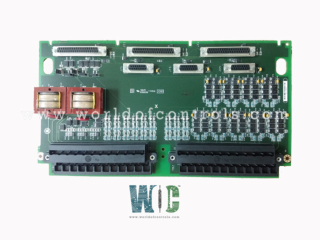
IS200TPROH2C - Emergency Protection Terminal Board

IS200TPROH2C - Emergency Protection Terminal Board IS200TPROH2C - Emergency Protection Terminal Board

World Of Controls understands the criticality of your requirement and works towards reducing the lead time as much as possible.

IS200TPROH2C - Emergency Protection Terminal Board is available in stock which ships the same day.

IS200TPROH2C - Emergency Protection Terminal Board comes in UNUSED as well as REBUILT condition.

To avail our best deals for IS200TPROH2C - Emergency Protection Terminal Board, contact us and we will get back to you within 24 hours.

SPECIFICATIONS

Part No.: IS200TPROH2C
Manufacturer: General Electric
Series: Mark VI
Size 17.8 cm Wide x 33.02 cm High
Function: I/O Module
MPU Pulse Rate Range 2 Hz to 20 kHz
Power Supply Voltage Input supply 28 V dc
MPU Pulse Rate Range 2 Hz to 20 kHz
Availability: In Stock
Country of Manufacture: United States (USA)

Functional Description

IS200TPROH2C is a Emergency Protection Terminal Board developed by GE. It is a part of mark VI control system. The Emergency Protection (TPRO) terminal board serves a critical role in providing the VPRO with essential input signals, such as speed signals, temperature signals, generator voltage, and bus voltage. These signals are an integral part of an independent emergency overspeed and synchronization protection system. The system consists of triple redundant VPRO boards, which are housed in a separate module from the main turbine control system. The VPRO boards are responsible for controlling the trip solenoids through the TREx (TREG, TREL, or TRES) terminal boards.

Installation

  • The terminal board serves as a central hub for various inputs used in the emergency overspeed and synchronization protection system. Different types of signals are wired to specific terminal blocks for processing and monitoring.
  • First Terminal Block: The first terminal block is dedicated to receiving signals from the generator and bus potential transformers, analog inputs, and thermocouples. The generator potential transformer provides voltage measurements from the generator windings, while the bus potential transformer measures voltage on the power distribution bus. These voltage measurements are essential for monitoring the electrical status of the generator and bus, ensuring safe and stable operation.
  • Analog inputs from various sensors are also connected to this terminal block. These analog inputs can represent a range of parameters, such as pressure, temperature, or flow rates. These inputs provide critical data for real-time monitoring of the turbine's operating conditions, enabling to detect any anomalies or abnormal conditions.
  • Additionally, thermocouples, which are temperature sensors based on the Seebeck effect, are also wired to this terminal block. Thermocouples are essential for measuring temperatures at different points in the turbine system. Monitoring temperature variations is crucial for ensuring the turbine operates within safe limits and preventing any potential damage due to overheating.
  • Second Terminal Block: The second terminal block is dedicated to magnetic speed pickups. These speed pickups are typically installed near rotating components in the turbine, such as shafts or rotors. They generate electrical signals in response to the turbine's rotational speed. Monitoring these signals allows the board to detect any abnormal speed variations, which may indicate overspeed conditions, and trigger the emergency overspeed protection function.
  • Jumpers JP1A and JP1B: Jumpers JP1A and JP1B are used to configure the first of the three analog inputs. Depending on the desired input signal type, these jumpers can be set to provide either a 4-20 mA current input or a voltage input. This flexibility allows for easy adaptation to various sensor types and ensures compatibility with different types of monitoring equipment. It gathers input signals from generator and bus potential transformers, analog inputs, thermocouples, and magnetic speed pickups, providing vital data for turbine monitoring and protection. The flexibility of jumpers JP1A and JP1B enables easy configuration of the analog input, making the board adaptable to different sensor types and input signal requirements.

Operation

  • The primary function is to provide critical speed signals to the VPRO, enabling emergency overspeed protection for the turbine. Beyond this, the module plays a vital role by supplying generator signals for backup synchronization check protection. It also facilitates three analog current inputs and nine thermocouple inputs, primarily dedicated to exhaust over-temperature protection on gas turbines.
  • One essential aspect of the TPRO-VPRO interaction is that the VPRO supplies 28 V dc to the TPRO. This power provision is crucial for energizing the three analog input transmitters, ensuring seamless data transmission and accurate monitoring of the analog inputs.

World of Controls has the most comprehensive collection of GE Mark VI components. Please contact WOC as soon as possible if you require any extra information.


Frequently Asked Questions


What is IS200TPROH2C?
It is a Emergency Protection Terminal Board developed by GE

How does VPRO perform diagnostic checks on TPRO and its input signals?
VPRO conducts diagnostic checks on TPRO and its input signals to ensure the system's integrity and reliability. It monitors analog inputs for high or low limit violations, and if any input exceeds these limits, a fault is triggered, indicating a potential issue.

What happens if any of the input signals become unhealthy?
If any of the input signals are deemed unhealthy or unreliable, VPRO activates a composite diagnostic alarm called L3DIAG_VPROR, L3DIAG_VPROS, or L3DIAG_VPROT (based on the specific signal source). This alarm signals the presence of a potential fault in the system that requires attention.

Can the diagnostic signals be latched individually?
Yes, the diagnostic signals can be individually latched by VPRO. When a diagnostic fault occurs, it can retain the fault status, allowing it to be easily identified and investigated. These latched diagnostic signals can be reset with the RESET_DIA signal when they become healthy again.

What information does the ID device on board connectors contain?
The terminal board connectors are equipped with an ID device containing crucial information. This read-only chip is coded with the terminal board's serial number, board type, revision number, and plug location. This data is essential for proper identification and compatibility checking during system operation.