SPECIFICATIONS
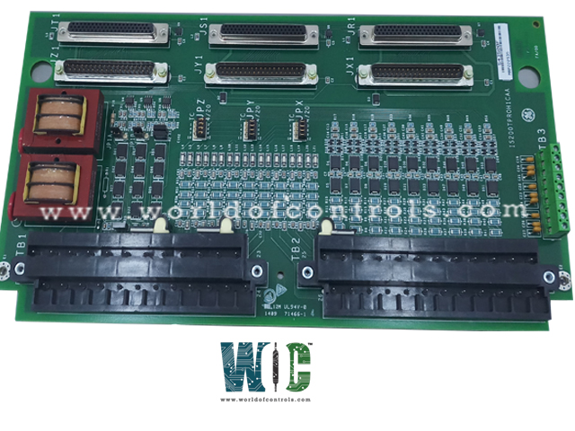
Part No.: IS200TPROH2B
Manufacturer: General Electric
Country of Manufacture: United States of America (USA)
MPU Pulse Rate Range: 2 Hz to 20 kHz
Number of Inputs: 22
Power Supply Voltage: Input supply 28 V dc
Analog Inputs:3
Input current: 4-20 mA
Size: 17.8 cm Wide x 33.02 cm High
Product Type: Emergency Protection Terminal Board
Availability: In Stock
Series: Mark VI
Functional Description
IS200TPROH2B is an Emergency Protection Terminal Board developed by GE. It is a part of Mark VI control system. Emergency Protection Terminal Board encompasses the provision of vital signals such as speed, temperature, generator voltage, and bus voltage to the Variable Protection (VPRO) system, forming an independent emergency overspeed and synchronization protection system.
Triple Redundancy and Module Separation
- Within the protection system, the triple redundancy of VPRO boards, combined with their isolation in a distinct module from the turbine control system, represents a cornerstone of reliability and safety. This design paradigm underscores a commitment to robustness and continuity of operations in critical scenarios.
- At the heart of the system lies the triple redundancy of VPRO boards, a testament to redundancy engineering at its finest. This triple-layered redundancy ensures that even in the event of multiple failures, the system can continue to operate reliably and maintain critical functions. Such redundancy minimizes the risk of catastrophic failure and underscores the system's resilience in adverse conditions.
- The decision to house the VPRO boards in a separate module from the turbine control system is strategic and deliberate. This physical separation serves to isolate critical functions, preventing potential interference or contamination from non-essential components. By minimizing single points of failure, this modular approach enhances system reliability and resilience, ensuring uninterrupted operation even in the face of unforeseen challenges.
- The VPRO boards, operating in concert, exert control over trip solenoids through TREx (TREG, TREL, or TRES). This coordinated effort ensures swift and synchronized responses to emergencies, allowing for rapid shutdown and mitigation of potential risks. By leveraging multiple redundant pathways, the system maximizes its responsiveness and robustness, safeguarding both equipment and personnel.
Product Features
- Interconnection and Signal Flow: TPRO serves as the central hub, supplying inputs to all three VPRO boards. Through meticulously configured cabling, it facilitates seamless communication between TPRO and TREx terminal boards, ensuring the smooth transmission of critical signals required for emergency overspeed and synchronization protection.
- Trip Solenoid Control: Up to three trip solenoids can be linked between TREx and TRPx (TRPG, TRPL, or TRPS) terminal boards. TREx provides the positive side of the 125 V DC to the solenoids, while TRPx supplies the negative side. This dual-sided control mechanism ensures redundancy and reliability, with either board capable of triggering turbine shutdown in emergency scenarios.
- Emergency Overspeed Protection and Control: The VPRO board takes center stage in emergency trip functions, providing overspeed protection and emergency stop capabilities. Through its control of 12 relays on TREG, it orchestrates the activation of trip solenoids, leveraging redundant groups of three relays to vote on critical inputs. Additionally, a secondary TREG board can be controlled from VPRO through J4, offering further redundancy and operational flexibility.
Magnetic Pickup (MPU)
- The Magnetic Pickup (MPU) serves as a vital component in systems requiring precise monitoring of rotational speed. Its characteristics, meticulously engineered to meet stringent performance requirements, ensure accurate signal transmission over extended distances.
- Output Specifications: The MPU boasts an output resistance of 200 ohms coupled with an inductance of 85 mH, facilitating impedance matching and minimizing signal distortion. Its output generates a peak-to-peak voltage of 150 V into a 60 K ohm load at the TPRO terminal block, delivering robust signal strength while mitigating the risk of sparking. Additionally, the MPU exhibits a maximum short circuit current of approximately 100 mA, safeguarding against overcurrent conditions.
- Normal Mode Load Application: To optimize signal fidelity and mitigate voltage fluctuations, the system applies up to a 400-ohm normal mode load to the MPU input signal. This load serves to stabilize voltage levels at the terminals, ensuring consistent and reliable signal transmission.
MPU Cable Specifications
- Sensors connected to the MPU can be located up to 300 meters (984 feet) from the cabinet, assuming the use of shielded pair cable.
- The cable exhibits typical characteristics including a single-ended capacitance of 70 nF or a differential capacitance of 35 nF, along with a resistance of 15 ohms. These specifications enable efficient signal propagation over extended distances while minimizing interference and signal degradation.
The WOC team is always available to help you with your Mark VI requirements. For more information, please contact WOC.
Frequently Asked Questions
What is IS200TPROH2B?
It is an Emergency Protection Terminal Board developed by GE under the Mark VI series.
What diagnostic checks does VPRO perform on TPRO and its cables?
VPRO conducts comprehensive diagnostic checks and its associated cables to ensure system integrity and reliability.
What triggers a fault in the diagnostic checks performed by VPRO?
If the analog inputs exceed predefined high or low limits, a fault is triggered, indicating potential issues requiring attention.
How does VPRO handle unhealthy signals from TPRO?
When any of the monitored signals become unhealthy, VPRO generates a composite diagnostic alarm known as L3DIAG VPROR (or S, or T), alerting operators to the issue. These diagnostic signals can be individually latched and subsequently reset using the RESET DIA signal once they return to a healthy state.
