SPECIFICATIONS
Part No.: IS200TBTCH1A
Manufacturer: General Electric
Country of Manufacture: United States of America (USA)
No.of Channels: 24
Technology: Surface-mount
Product Type: Thermocouple Terminal Board
Availability: In Stock
Series: Mark VIe
Functional Description
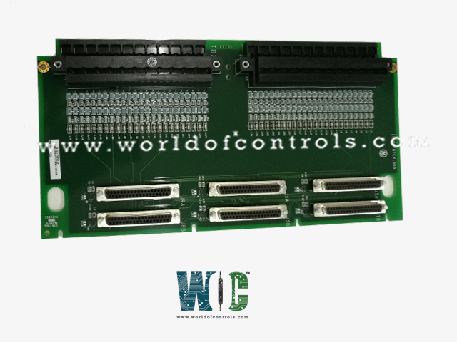
IS200TBTCH1A is a thermocouple terminal board developed by GE. It is part of Mark VIe series. The thermocouple terminal board serves as a hub for 24 different types of thermocouple inputs, including E, J, K, S, or T. These inputs are specifically wired to two barrier-type blocks integrated onto the terminal board. Communication between these inputs and the I/O processor is established through D-type connectors, ensuring seamless data transmission.
PTCC I/O Pack Integration in Mark VIe System
- Collaboration with Board: The PTCC I/O pack closely collaborates with the board within the Mark VIe system. This collaboration facilitates seamless integration and communication between the PTCC inputs and the system processor, enabling accurate monitoring and control of pressure and temperature parameters.
- Support for Various System Configurations: The integration of PTCC I/O packs with the board supports a wide range of system configurations, including simplex, dual, and TMR (Triple Modular Redundancy) systems. This versatility enables operators to tailor the system architecture to meet specific requirements and redundancy needs.
- Configuration with TBTCH1C: In simplex systems utilizing the TBTCH1C, two PTCC packs can be accommodated, providing a total of 24 inputs. This configuration offers enhanced scalability and flexibility in system design, catering to diverse application demands.
- Configuration with TBTCH1B: Using the TBTCH1B variant alters the system configuration, offering greater flexibility in the number of PTCC packs that can be plugged in. This flexibility allows for the accommodation of one, two, or three PTCC packs, depending on the system requirements.
- Impact on Available Inputs: Despite the versatility offered by the TBTCH1B configuration, there is a trade-off in the number of available inputs. While TBTCH1C allows for 24 inputs in simplex systems, the TBTCH1B configuration limits the available inputs to 12. Operators must consider this limitation when designing and configuring the system for specific applications.
Input Specifications and Location
- The 24 thermocouple inputs within the board can be either grounded or ungrounded. Furthermore, they can be situated up to a distance of 300 meters (approximately 984 feet) from the turbine control panel, provided the maximum two-way cable resistance does not exceed 450 ohms.
- The analog-to-digital conversion takes place within the I/O processor, handles the crucial task of linearization for individual thermocouple types, ensuring accurate and reliable data acquisition and processing.
Installation Procedure Guidelines
- In the system configuration, the thermocouples establish a direct connection to two I/O terminal blocks. These blocks, which are detachable components, are securely mounted onto the terminal board using two screws, ensuring stability and robust connectivity. Each of these blocks comprises 24 terminals, capable of accommodating wires of up to #12 AWG gauge, facilitating seamless integration of the thermocouples into the system.
- The terminal blocks, essential components of the setup, provide the necessary interface for connecting the thermocouples. Adjacent to each terminal block, a shield terminal strip is positioned on the left side. This strip serves the purpose of connecting to the chassis ground, contributing to system grounding and shielding, thereby enhancing overall stability and safety.
- In Mark VI systems, the connectivity extends from the board's J-type connectors to the I/O processors situated within the VME (Versa Module Eurocard) rack. This wiring setup facilitates communication and data transmission between the thermocouples and the I/O processors in the rack, ensuring efficient processing and control.
- The number of cables or I/O packs utilized in this configuration is contingent upon the desired level of redundancy required for the system. This modularity enables adaptable redundancy levels, providing flexibility in system design tailored to specific operational needs and requirements.
The WOC team is always available to help you with your Mark VIe requirements. For more information, please contact WOC.
Frequently Asked Questions
What is IS200TBTCH1A?
It is a Thermocouple Terminal Board developed by GE under the Mark VIe series.
What is Hardware Limit Checking for thermocouples?
Each thermocouple type incorporates preset high and low levels positioned close to the operational range ends. If these limits are exceeded, it triggers a logic signal, resulting in the discontinuation of scanning for that input. If any input reaches its hardware limits, a composite diagnostic alarm is generated, indicating potential issues.
What information is stored in the terminal board connector's ID device?
Every terminal board connector contains its unique ID, device interrogated by the I/O board. This device holds crucial data such as the terminal board's serial number, board type, revision number, and the specific location of the J connector. If there's a discrepancy, a hardware incompatibility fault is flagged, alerting to potential hardware issues.
Why is a small current injected into thermocouple paths when operating with the I/O board?
A minute current is introduced into each thermocouple path to detect open circuits. This current is intentionally polarized to simulate a high-temperature reading in case a thermocouple circuit opens. This setup allows for efficient detection of potential issues, ensuring system reliability.
What happens if any of the thermocouples exceed their hardware limits?
Exceeding the hardware limits of any thermocouple triggers a logic signal, leading to the discontinuation of scanning for that particular input. Additionally, if any input reaches its hardware limits, it contributes to the creation of a composite diagnostic alarm, indicating potential system issues.
