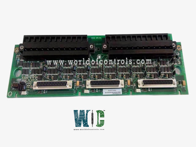
World Of Controls understands the criticality of your requirement and works towards reducing the lead time as much as possible.
IS200TBQBH2A - Analog I/O Terminal Board is available in stock which ships the same day.
IS200TBQBH2A - Analog I/O Terminal Board comes in UNUSED as well as REBUILT condition.
To avail our best deals for IS200TBQBH2A - Analog I/O Terminal Board, contact us and we will get back to you within 24 hours.
TECHNICAL SPECIFICATIONS
Part Number: IS200TBQBH2A
Manufacturer: General Electric (GE)
Series: Mark VI
Product Type: Analog I/O Terminal Board
Board Type: DIN-Rail / Cabinet Mount Terminal Board
Application: General Purpose Analog Signal Interfacing
Functional Group: TBQB (Analog Terminal Board)
Revision: Functional Revision H2A
Input Circuits: Analog Inputs (0–10 V DC, ±10 V DC, 4–20 mA Current Loop)
Output Circuits: Analog Outputs (4–20 mA Sourcing)
Terminal Block Interface: Screw-Type Barrier Terminal Blocks
I/O Pack Compatibility: Mounts Direct D-Sub / Ribbon Interfaces to I/O Packs
Shield Terminals: Grounding Terminals for Shielded Field Wiring
Conformal Coating: Yes
System Compatibility: GE Mark VI / Mark VIe Systems
Availability: In Stock
Repair Lead Time: 3–7 Days
Country of Origin: United States
Manual Reference: GEH-6421
The GE IS200TBQBH2A is an Analog I/O Terminal Board (TBQB) designed and manufactured by General Electric as part of the Speedtronic Mark VI gas turbine control framework. Positioned within the decentralized I/O layer, this board functions as the physical landing zone for critical mechanical feedback instrumentation, specifically routing voltage, vibration, and pulse rate frequency inputs. The H2A revision delivers an upgraded, highly stable board layout optimized to suppress high-frequency noise and safeguard central processing engines from field-side electrical surges.
CORE ROUTING AND INTERFACE DYNAMICS
The physical layout of the TBQBH2A is designed for placement in position seven within the R2 and R3 controller cores. When positioned in the R2 core, the board aggregates external inputs and distributes them to the TCQA and TCQC processing cards located in the R1 core. Conversely, when configured within the R3 core, it forms localized communication loops, connecting directly to the internal TCQA and TCQC processing hardware inside the same R3 core structure.
DUAL CONNECTOR ARCHITECTURE (JGR / JHR)
System interconnectivity is split across two high-density multi-pin arrays to keep disparate signal categories isolated:
HARDWARE CONFIGURATION:
BURDEN RESISTOR AND SIGNAL CONDITIONING HARDWARE
The circuit board features onboard hardware jumpers categorized from BJ1 through BJ7 to allow variable field commissioning adjustments. Jumpers BJ1 to BJ4 are used to split and route the pressure transducer 1 input signal intended for active compressor stall warning logic. When combined with the configuration of jumpers BJ5 to BJ7, the board introduces a hardware burden resistor into the loop. This physical circuit modification converts the primary transducer input from a voltage format into a structured current format, preventing signal degradation over lengthy field wiring runs.
WHY BUY FROM WOC
World of Controls maintains the industry's largest inventory of genuine OEM replacement components exclusively for GE Speedtronic control systems. To minimize critical plant downtime, we provide both UNUSED surplus and fully REBUILT circuit boards, processor cards, and I/O modules, each backed by comprehensive warranty protection. Every reconditioned Speedtronic component undergoes thorough diagnostic testing, circuit-level evaluation, and functional bench-testing by our experienced technical team before dispatch. In addition to direct parts supply, our facility offers complete diagnostic repair and unit exchange services with rapid turnaround times for your damaged GE Speedtronic hardware. Our dedicated team of automation specialists is available 24/7 to assist with technical selection, stock verification, and emergency component sourcing for your Speedtronic control panels. Contact us today via phone or email to request pricing, confirm live inventory, or discuss custom repair solutions for your GE Speedtronic infrastructure.
FREQUENTLY ASKED QUESTIONS
What is the GE IS200TBQBH2A?
It is an Input Termination Module (TBQB) designed for GE Speedtronic Mark VI control systems. It acts as a dedicated terminal interface that accepts field wiring for vibration, voltage, and high-frequency pulse rate signals, routing them to core processing boards.
Where is this module physically located within the Mark VI control panel?
The module mounts directly onto a standard DIN rail and is specifically positioned in slot/position seven within the R2 and R3 controller cores of the Mark VI cabinet layout.
How does the cross-core signal routing differ between the R2 and R3 installations?
When the board is mounted in the R2 core, it routes its telemetry data across to the TCQA and TCQC cards in the R1 core. When installed in the R3 core, it connects directly to the TCQA and TCQC cards within that same R3 core.
What specific data streams are split between the JGR and JHR faceplate connectors?
The JGR connector routes high-speed vibration signals and general analog current/voltage metrics to the TCQA card. The JHR connector isolates pulse rate inputs (like magnetic speed pickups) and compressor stall indicators, routing them to the TCQC board.
What is the purpose of hardware jumpers BJ1 through BJ7 on the board?
These jumpers configure the input formatting for the primary compressor stall pressure transducer. Jumpers BJ1–BJ4 split the incoming signal, while BJ5–BJ7 switch an internal burden resistor into the path to convert the transducer signal from a voltage format into a current format.
Can the IS200TBQBH2A be used simultaneously with a QTBA terminal board for the same inputs?
No. While some field signals can land on either a PTBA or a QTBA terminal board, the signals must not be duplicated. If a specific input path is wired and terminated on the primary board, the corresponding screw terminals on the auxiliary terminal board are omitted or must be left completely unpopulated.