World Of Controls understands the criticality of your requirement and works towards reducing the lead time as much as possible.
IS200TBCIH4C - Contact Input Group Isolation Terminal Board is available in stock which ships the same day.
IS200TBCIH4C - Contact Input Group Isolation Terminal Board comes in UNUSED as well as REBUILT condition.
To avail our best deals for IS200TBCIH4C - Contact Input Group Isolation Terminal Board, contact us and we will get back to you within 24 hours.
SPECIFICATIONS:
Part Number: IS200TBCIH4C
Manufacturer: General Electric
Series: Mark VIe
Product Type: Contact Input Group Isolation Terminal Board
Number of channels: 24
Power supply voltage: 28 V dc
Voltage Range: 14 to 32 V dc
Mounting: DIN-rail mounting
Technology: Surface mount
Operating temperature: -30 to 65°C
Size: 33.02 cm high x 17.8 cm
Repair: 3-7 Days
Availability: In Stock
Country of Origin: United States
FUNCTIONAL DESCRIPTION:
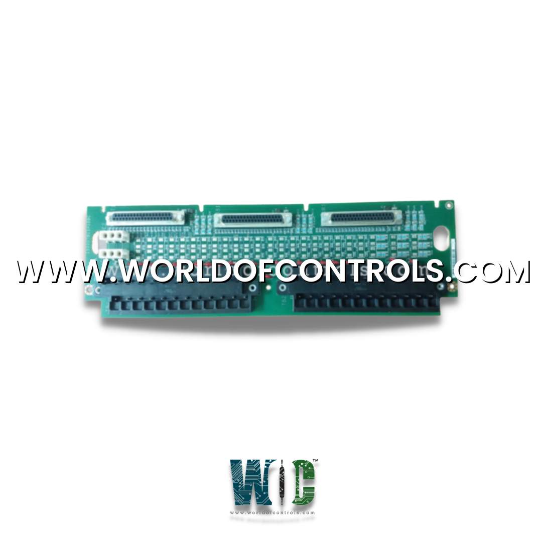
IS200TBCIH4C is a Contact Input Group Isolation Terminal Board manufactured and designed by General Electric as part of the Mark VIe Series used in GE Distributed Turbine Control Systems. The Contact Input with Group Isolation (TBCI) terminal board accepts 24 dry contact inputs wired to two barrier-type terminal blocks. For contact excitation, dc power is wired to TBCI. The contact inputs have noise suppression circuitry to protect against surges and high-frequency noise. The TBCI works with the PDIA I/O pack and supports simplex, dual, and TMR applications. One, two, or three PDIAS can be plugged directly into the TBCI. The Mark Vle control requires the C version of this board for correct mechanical alignment of connector JTI to the I/O pack mechanical support.
INSTALLATION:
Connect the wires for the 24 dry contact inputs directly to two I/O terminal blocks on the terminal board. These blocks are held down with two screws and can be unplugged from the board for maintenance. Each block has 24 terminals accepting up to #12 AWG wires. A shield terminal strip attached to the chassis ground is located immediately to the left of each terminal block.
In a simplex system, connect the TBCI to the PDIA I/O pack using connector JR1. In a TMR system, connect TBCI to the three PDIAS using connectors JR1, JS1, and JT1. The PDIAS plug into TBCI and attach to side-mounting brackets. One or two Ethernet cables plug into the I/O pack. Firmware may need to be downloaded. Connect TBCI to the contact excitation voltage source using plugs JE1 and JE2.
OPERATION:
Filters reduce high-frequency noise and suppress surge on each input near the point of signal entry. The dry contact inputs on TBCI_IC are powered from a floating 125 V de (100-145 V dc) supply from the turbine control. The 125 V de bus is currently limited in the power distribution module before feeding each contact input. The H2, H3, and H4 versions use lower voltages.
The discrete input voltage signals pass to the PDIA I/O pack, which sends them through optical isolators providing group isolation and transfers the signals to the Mark VIe controller. The reference voltage in the isolation circuits sets a transition threshold that is equal to 50% of the applied floating power supply voltage. The tracking is clamped to go no less than 13% of the nominal rated supply voltage to force all contacts to indicate open when the voltage dips below this level.
A pair of terminal points is provided for each input, with one point (screw) providing the positive de-source and the second point providing the return (input) to the board. The current loading is 2.5 mA per point for the first 21 inputs on each terminal board. The last three have a 10 mA load to support the interface with remote solid-state output electronics. Contact input circuitry is designed for NEMA Class G creepage and clearance.
DIAGNOSTICS:
WOC offers the largest stock of OEM replacement parts for GE Distributed Turbine Control Systems and provides expert repair services for faulty boards, as well as unused and rebuilt units, all backed by a warranty. Our team of specialists is available 24/7 to support your OEM and automation needs, ensuring minimal downtime and reliable system performance. For pricing, availability, or technical assistance, please contact our team by phone or email, and we’ll provide prompt, professional guidance tailored to your requirements.
How is the input current load handled on the terminal board?
The current load for the first 21 inputs on the terminal board is 2.5 mA per point, while the last 3 inputs require a 10 mA load to interface with remote solid-state output electronics.
What is the excitation voltage required for operation?
The excitation voltage for the contact inputs is provided by a floating 125 V dc (100-145 V dc) supply from the turbine control. If this voltage drops below 40% of the nominal value, it triggers a diagnostic alarm.
How does the terminal board handle input signal isolation?
The terminal board uses optical isolators to provide group isolation for the contact input signals. These isolators separate the signals to prevent electrical interference and ensure the signals are clean before being sent to the Mark VIe controller.