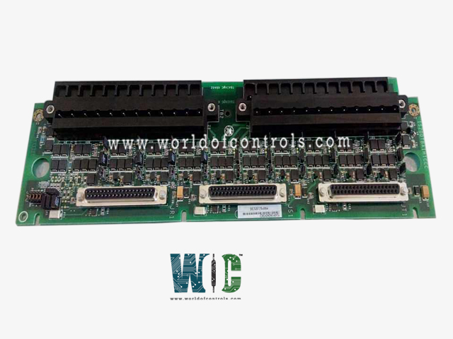
IS200TBAIH1CDD - Analog Input Terminal Board

IS200TBAIH1CDD - Analog Input Terminal Board IS200TBAIH1CDD - Analog Input Terminal Board

World Of Controls understands the criticality of your requirement and works towards reducing the lead time as much as possible.

IS200TBAIH1CDD - Analog Input Terminal Board is available in stock which ships the same day.

IS200TBAIH1CDD - Analog Input Terminal Board comes in UNUSED as well as REBUILT condition.

To avail our best deals for IS200TBAIH1CDD - Analog Input Terminal Board, contact us and we will get back to you within 24 hours.

SPECIFICATIONS

Part No.: IS200TBAIH1CDD
Manufacturer: General Electric
Country of Manufacture: United States of America (USA)
Temperature: -30 to 65 oC (-22 to +149 oF)
Size: 10.16 cm wide x 33.02 cm high
Product Type: analog input terminal board
Availability: In Stock
Series: Mark VIe

Functional Description

IS200TBAIH1CDD is an analog input terminal board developed by GE. It is a part of Mark VIe control system. The Analog Input Terminal Board (TBAI) is designed to facilitate the integration of analog inputs and outputs within a control system. It is equipped to handle 10 analog inputs, offering versatility to accommodate various types of transmitters. These inputs support two-wire, three-wire, four-wire, or externally powered transmitters, providing flexibility for different sensor configurations.

Features

  • Analog Output Configurability: The two analog outputs can be configured for either 0-20 mA or 0-200 mA current. This configurability enhances adaptability to specific system requirements and allows for precise control over the current output levels.
  • Noise Suppression Circuitry: Both inputs and outputs are equipped with noise suppression circuitry. This feature acts as a safeguard, protecting the system from surge and high-frequency noise that could potentially interfere with the accuracy and reliability of analog signals.
  • Connector Configuration: Features three DC-37 pin connectors, labeled JR1, JS1, and JT1, designed for seamless connection to I/O processors. These connectors offer flexibility in the configuration of connections, supporting both simplex and Triple Modular Redundant (TMR) setups.
  • Connection Modes: Connections to the I/O processors can be established in simplex mode using a single connector (JR1), or in TMR mode utilizing all three connectors (JR1, JS1, and JT1). This adaptability allows for the tailoring of the connection architecture to suit specific system requirements.
  • TMR Application Operation: In TMR applications, the input signals are fanned out to the three connectors (JR1, JS1, and JT1) for the R, S, and T controls. TMR outputs operate by combining the current output of the three connected drivers. The total current is determined using a measuring shunt on the TBAI. This total current signal is then presented to the electronics for regulation to the commanded setpoint.
  • Signal Combining in TMR: TMR outputs employ a unique mechanism where the current from three connected output drivers is combined. This process ensures redundancy and fault tolerance, as the total current can be accurately measured and regulated even in the event of a failure in one of the channels.
  • Regulation and Setpoint Control: The TBAI plays a crucial role in the regulation of total current signals to meet the commanded setpoint. This function ensures that the output currents, in both simplex and TMR configurations, align with the desired control parameters, contributing to the overall stability and accuracy of the control system.

Configuration

  • J1A through J8A - Input Type Selection: These jumpers are responsible for selecting the input type for channels 1 through 8. The options include current input or voltage input. The specific configuration for each channel is determined by the setting of these jumpers, offering versatility in adapting to different sensor types.
  • J1B through J8B - Return Connection: These jumpers are dedicated to selecting whether the return is connected to the common or left open for channels 1 through 8. The configuration of these jumpers influences how the return path is established, providing flexibility in grounding configurations.
  • J9A and J10A - Input Current Selection: J9A and J10A jumpers are responsible for selecting either 1 mA or 20 mA input current for the respective channels. This choice allows users to match the input current to the specifications of the connected sensors, ensuring accurate and reliable signal processing.
  • J9B and J10B - Return Connection for Current Selection: These jumpers, J9B and J10B, determine whether the return for the selected input current (1 mA or 20 mA) is connected to the common or left open. This configuration choice influences the grounding scheme for the selected input current.
  • J0 - Output 1 Configuration: Jumper J0 is utilized to set the configuration of Output 1. Users can choose between 20 mA or 200 mA output current based on the specific requirements of the control system. This flexibility ensures compatibility with various downstream components.
  • Toolbox Configuration for VAIC or PAIC: While the mentioned jumpers handle the fundamental input and output configurations, other aspects related to VAIC (Voltage-to-Current Converter) or PAIC (Pulse Amplitude-to-Current Converter) are configured using the toolbox. The toolbox serves as a comprehensive interface for advanced configuration options, allowing users to fine-tune the performance of the TBAI based on specific system requirements.
  • Flexibility and Adaptability: The configuration options provided by the jumpers offer a high degree of flexibility and adaptability. Users can tailor to match the characteristics of connected sensors and devices, optimizing the overall performance of the analog input terminal board.

The WOC team is always available to help you with your Mark VIe requirements. For more information, please contact WOC.

Frequently Asked Questions

What is IS200TBAIH1CDD?
It is an analog input terminal board developed by GE under the Mark VIe series.

How does the board indicate the output current?
The Analog Input Terminal Board employs a series resistor to measure the voltage drop across it, providing an indication of the output current. This mechanism enables the board to monitor and report the current status, contributing to effective diagnostics and fault detection.

What happens if any one of the two outputs goes unhealthy?
In the event of any one of the two outputs going unhealthy, the I/O processor generates a diagnostic alarm or fault. This proactive approach ensures that potential issues with the outputs are promptly identified, allowing for timely intervention and system maintenance.

How does the TBAI handle hardware incompatibility issues?
Each cable connector is equipped with its own ID device -a read-only chip containing crucial information such as the terminal board serial number, board type, revision number, and connector location (JR, JS, JT). If a mismatch is detected between the read information and the expected configuration, a hardware incompatibility fault is generated. This mechanism ensures that only compatible components are integrated into the system.

What is the purpose of the ID device on each cable connector?
The ID device on each cable connector serves as a unique identifier. It contains essential information that includes the serial number, board type, revision number, and connector location. This information is read by the I/O controller during system checks, helping to prevent hardware incompatibility and ensuring seamless integration.

How does the diagnostic alarm for unhealthy outputs contribute to system reliability?
The diagnostic alarm triggered by unhealthy outputs serves as an early warning system. By promptly identifying and reporting issues with the outputs, the system can initiate corrective actions or enter a safe state. This proactive approach enhances overall system reliability and minimizes the risk of extended downtime.

Can the ID device information be accessed by the I/O controller for troubleshooting?
Yes, the I/O controller can access the information stored in the ID device for troubleshooting purposes. This information, including the serial number, board type, revision number, and connector location, assists in identifying specific components, ensuring proper configuration, and facilitating efficient diagnostics in case of any discrepancies.