SPECIFICATIONS
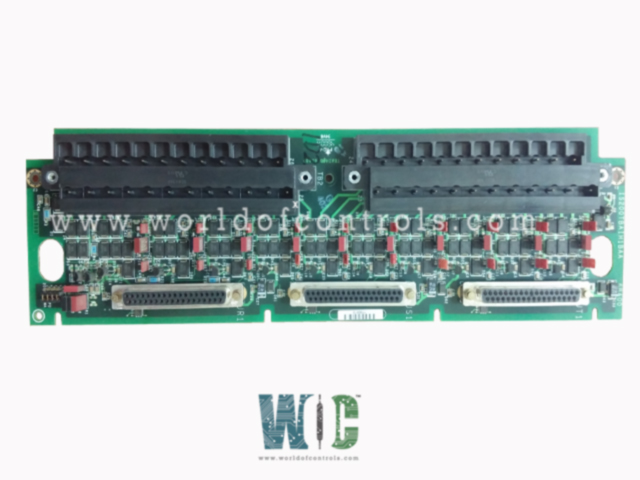
Part No.: IS200TBAIH1BAA
Manufacturer: General Electric
Country of Manufacture: United States of America (USA)
Temperature: -30 to 65oC
Size: 10.16 cm wide x 33.02 cm high
Product Type: Analog Input/Output Terminal Board
Availability: In Stock
Series: Mark VI
Functional Description
IS200TBAIH1BAA is an analog input/output terminal board developed by GE. It is a part of Mark VI control system. In the Mark VI system, the board plays a crucial role in conjunction with the VAIC processor, supporting both simplex and TMR (Triple Modular Redundancy) applications. It is designed to seamlessly integrate with the VAIC processor, forming a key component of the system's input/output infrastructure. It communicates with the VAIC processor to facilitate the transmission and reception of analog input and output signals.
Support for Simplex and TMR Applications
- TBAI offers versatile support for both simplex and TMR configurations, providing flexibility in system design and redundancy options.
- In simplex applications, a single board can be connected to the VAIC processor, enabling efficient analog signal processing.
- For TMR systems, where redundancy and fault tolerance are paramount, up to three boards are cabled to three VAIC boards, enhancing system reliability through redundancy.
Features
- Analog Inputs and Outputs: Accommodates 10 analog inputs and 2 outputs. Inputs support various transmitter types: two-wire, three-wire, four-wire, or externally powered. Analog outputs can be configured for either 0-20 mA or 0-200 mA current.
- Noise Suppression and Protection: Both inputs and outputs feature noise suppression circuitry, safeguarding against surge and high-frequency noise disruptions.
- Connectivity: TBAI offers three DC-37 pin connectors for connection to I/O processors. Simplex applications utilize a single connector (JR1), while TMR applications utilize all three connectors.
- TMR Functionality: In TMR applications, input signals are distributed across the R, S, and T connectors. TMR outputs amalgamate the current from the three connected drivers, determining the total current using a measuring shunt. Delivers the total current signal to the I/O processors for regulation according to the commanded setpoint.
Fault Detection
Fault detection is a critical aspect of ensuring the reliability and safety of the system. Here's how fault detection is implemented on the terminal board:
- Monitoring Total Output Current: The board continuously monitors the total output current to detect any anomalies or deviations from the expected values.
Any significant variations or abnormalities in the total output current trigger the fault detection mechanism, indicating a potential issue that requires attention.
- Connector ID Chip Verification: The board verifies the connector ID chip to ensure hardware compatibility and integrity.
If a mismatch or inconsistency is detected in the connector ID chip, indicating hardware incompatibility or potential faults, the fault detection system is activated.
Installation Procedure
- Prepare the terminal blocks: Locate the two I/O terminal blocks mounted on the terminal board. Each terminal block is secured in place with two screws for stability during installation.
- Connect Input and Output Wires: Identify the input and output wires designated for connection to the terminal board. Directly insert the wires into the corresponding terminals on the terminal blocks. Ensure that the wires are securely inserted and make proper contact with the terminals.
- Secure Terminal Blocks: Tighten the screws on each terminal block to securely hold the inserted wires in place. Verify that the connections are tight and free from any loose wires to prevent potential electrical hazards.
- Shield Terminal Attachment: Adjacent to each terminal block, locate the shield terminal attachment points. If shielding is required for specific applications, attach the shield terminals to ensure proper grounding and noise suppression.
- Final Inspection: Conduct a visual inspection to confirm that all connections are properly made and secured. Check for any loose wires or terminals and rectify any issues before proceeding.
Characteristics
- Number of channels: 12 channels per terminal board (10 AI, 2 AO)
- Input span, transmitters: 1-5 V dc from 4-20 mA current input
- Outputs: 24 V outputs provide 21 mA each connection
- Maximum lead resistance: 15 maximum two-way cable resistance, cable length up to 300 m (984 ft)
The WOC team is always available to help you with your Mark VI requirements. For more information, please contact WOC.
Frequently Asked Questions
What is IS200TBAIH1BAA?
It is an analog input/output terminal board developed by GE under the Mark VI series.
What power source is provided for transducers?
It supplies a 24 V dc power source for all connected transducers, ensuring consistent and reliable operation.
How are the inputs configured on the terminal board?
Inputs on the board can be configured as either current or voltage inputs using jumpers labeled J#A and J#B, providing flexibility in signal processing.
What are the analog output configurations supported by TBAI?
TBAI features two analog output circuits. One circuit supports a 4-20 mA configuration, while the other can be configured as either 4-20 mA or 0-200 mA, offering versatility in output signal ranges.
