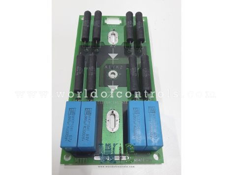
World Of Controls understands the criticality of your requirement and works towards reducing the lead time as much as possible.
IS200RCSAG1ABB - 1800/1000 Frame RC Snubber Board is available in stock which ships the same day.
IS200RCSAG1ABB - 1800/1000 Frame RC Snubber Board comes in UNUSED as well as REBUILT condition.
To avail our best deals for IS200RCSAG1ABB - 1800/1000 Frame RC Snubber Board, contact us and we will get back to you within 24 hours.
SPECIFICATIONS:
Part No: IS200RCSAG1ABB
Manufacturer: General Electric
Function: 1800/1000 Frame RC Snubber Board
Series: Mark VI Speedtronic / EX2100
Operating temperature: -35 to 65 ºC
Power Supply Voltage: 25 V dc
Ethernet UDH: High-speed communication
PCB Coating: Normal
Board Size: 23.8 cm high x 8.6 cm
Weight: 0.45 kgs
Availability: In Stock
Country of Origin: USA
Manual: GEI-100303
FUNCTIONAL DESCRIPTION:
IS200RCSAG1ABB is a 1800/1000 Frame RC Snubber Board manufactured and designed by General Electric as part of the EX2100 Series used in the GE Excitation Control System. Its primary function is to protect power semiconductors—typically silicon-controlled rectifiers (SCRs)—from high-voltage transients that occur during switching. When SCRs rapidly transition between on and off states, they can generate sharp voltage spikes due to the system’s inductive load. The RCSAG1A board mitigates these spikes by absorbing and dissipating excess energy through a resistor-capacitor (RC) network. This helps prevent electrical overstress, minimizes electromagnetic interference (EMI), and reduces the likelihood of component failure or insulation damage. In high-power applications, such protection is critical for ensuring long-term reliability and maintaining the safe operation of the excitation bridge.
SNUBBER CIRCUIT:
Each board includes two identical resistor-capacitor (R/C) snubber circuits—one associated with the SCR and the other with the diode. These snubber circuits are designed to suppress voltage transients and limit the rate of voltage rise (dv/dt) across the power devices, which helps prevent unintentional triggering of the SCR and reduces electrical stress on both components. The power device is connected across its corresponding snubber network, with the R/C circuit bridging the anode and cathode terminals. This configuration ensures effective damping of switching transients and improved reliability and longevity of the power semiconductor devices during high-speed switching operations or in the presence of inductive loads. Proper snubber operation also contributes to enhanced electromagnetic compatibility (EMC) by minimizing voltage spikes that could otherwise propagate through the system.
APPLICATION DATA:
The RCSA board is a passive, support-oriented circuit board designed without any onboard active components or user-accessible features. It does not include fuses, test points, LED indicators, or any movable hardware, emphasizing its role as a dedicated snubber interface for power devices rather than a diagnostic or control module. Each board is mechanically and electrically supported by the corresponding SCR/diode module for each phase. These power modules not only serve as the functional components in the circuit but also act as the primary mounting structure for the RCSA board, ensuring a compact and efficient assembly.
WOC has the largest stock of GE Excitation Turbine Control System Replacement Parts. We can also repair your faulty boards and supply unused and rebuilt boards backed up with a warranty. Our team of experts is available around the clock to support your OEM needs. Our team of experts at WOC is happy to assist you with any of your automation requirements. For pricing and availability on any parts and repairs, kindly get in touch with our team by phone or email.
What is the purpose of the RC snubber board in 1800/1000 frame systems?
The RC snubber board is used to suppress voltage transients and limit the dv/dt across SCRs and diodes during switching operations. It enhances the reliability and longevity of power semiconductor devices by reducing electrical stress.
How is the RCSA board mounted?
The board is mounted directly onto the SCR/diode module for each phase, which provides both mechanical support and electrical connection. Additionally, there are four holes at the corners for securing the board using wire ties.
How many snubber circuits are implemented per board, and how are they configured?
Each RCSA board includes two discrete R-C snubber circuits—one for the SCR and one for the anti-parallel diode. Each snubber is connected from anode to cathode of the respective device, forming a parallel damping network across the power terminals.