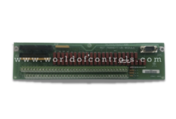
World Of Controls understands the criticality of your requirement and works towards reducing the lead time as much as possible.
IS200QTBAH2A - Analog I/O Termination Module is available in stock which ships the same day.
IS200QTBAH2A - Analog I/O Termination Module comes in UNUSED as well as REBUILT condition.
To avail our best deals for IS200QTBAH2A - Analog I/O Termination Module, contact us and we will get back to you within 24 hours.
SPECIFICATIONS:
Part Number: IS200QTBAH2A
Manufacturer: General Electric
Series: Mark VI
Product Type: Analog I/O Termination Module
Input Signal Types: 0–1 mA
Technology: Surface mount
Operating Voltage: 24 V DC
Operating temperature: 40 to 70°C
Output Signal: 0–1 mA
Size: 17.8 cm high x 33.02 cm
Repair: 3-7 days
Availability: In Stock
Country of Origin: United States
Manual: GEH-6421M
FUNCTIONAL DESCRIPTION:
IS200QTBAH2A is an Analog I/O Termination Module manufactured and designed by General Electric as part of the Mark VI Series used in GE Speedtronic Gas Turbine Control Systems. The Termination Module (QTBA) is located in the R1, R2, and R3 cores. The QTBA terminal board lands the signals used by the TCQC board in the respective cores. The COREBUS connections are on the QTBA terminal boards. The inputs for pulse rates and megawatt transducers are landed on the QTBA terminal board and written to the TCQC board. The outputs for the LVDT/R excitation and servo valve outputs are written to the QTBA terminal board from the TCQC board. The Terminal Interface Monitor (TIMN) connections are also located on the QTBA terminal board. A bypass relay that allows the COREBUS to continue to communicate if power is lost on the QTBA terminal board is located on the QTBA terminal board.
QTBA CONNECTIONS:
JAI – COREBUS Connection: The JAI connector serves as a communication interface within the COREBUS system architecture, facilitating data transfer between system components. It is crucial for maintaining the integrity and performance of the bus network. In configurations where the JAI connection is not actively used, a termination resistor must be installed at the connector.
JAJ – COREBUS Connection: The JAJ connector functions similarly to JAI by providing an additional communication pathway on the COREBUS network. It supports the coordinated exchange of control and status signals between system modules.
JEE – I/O Signal Communication with STCA Board: The JEE connection acts as a dedicated interface for transmitting Input and Output (I/O) signals between the COREBUS and the STCA (Signal Transducer and Control Assembly) board. This connection enables the COREBUS to monitor and control various peripheral devices and sensors connected through the STCA.
JGG – Interface for Signal Exchange with TCQC Board: The JGG connection manages the transmission and reception of vital analog and digital signals between the core system and the TCQC (Turbine Control Quadrature Converter) board. Specifically, it writes milliampere (mA) input signals, pulse rate input signals, and megawatt transducer signals to the TCQC board.
JFF – LVDT/R Excitation and Servo Output Signal Transmission: The JFF connection is responsible for transmitting excitation signals to the Linear Variable Differential Transformer (LVDT) or Resolver (R) sensors, as well as sending servo output signals to the TCQC board within the respective core. These signals provide the necessary feedback for position sensing and control in turbine servomechanisms.
JRS – RS232 Monitor Signal Reception: The JRS connector is used to read RS232 serial monitor signals from various system modules. This interface enables the retrieval of diagnostic data, status information, and communication logs via the RS232 protocol, which is widely used for serial communication and system monitoring.
HARDWARE CONFIGURATION:
The milliamp input signal is a standard analog current signal used widely for industrial sensors and transducers to represent process variables. The selection between two common current ranges — 0–1 mA or 4–20 mA — is essential because different field devices output different standard signal ranges. Proper configuration ensures compatibility, accuracy, and prevents signal misinterpretation.
WOC has the largest stock of OEM replacement parts for GE Speedtronic Gas Turbine Control Systems. We can also repair your faulty boards and supply unused and rebuilt boards backed up with a warranty. Our team of experts is available around the clock to support your OEM needs. Our team of experts at WOC is happy to assist you with any of your automation requirements. For pricing and availability on parts and repairs, kindly contact our team by phone or email.
What is the typical resistance value of termination resistors in an Analog I/O Termination Module?
Common termination resistor values range from 120 Ohms to 330 Ohms, selected to match the characteristic impedance of the signal cable or bus.
How does the thermocouple board differ in terms of fan-out capability?
There are two versions of the thermocouple board. One version does not fan out and has two connectors for cabling to one I/O board, while the other version fans out with six connectors for R, S, and T connections.
Why is the fan-out circuit considered a potential single point of failure?
The fan-out circuit is a potential single point of failure because, in certain configurations, it plays a critical role in distributing signals. To mitigate this risk, the terminal board contains minimal active circuitry, primarily consisting of filters and protective devices.