World Of Controls understands the criticality of your requirement and works towards reducing the lead time as much as possible.
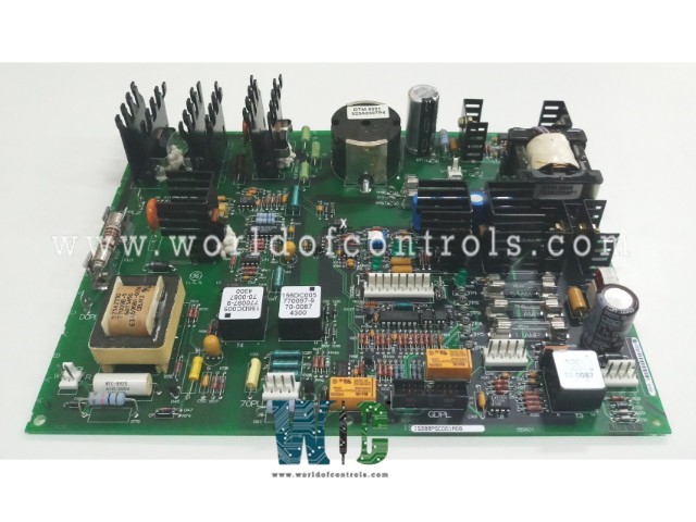
IS200PSCDG1ABB - Power Supply and Contactor Driver Board is available in stock which ships the same day.
IS200PSCDG1ABB - Power Supply and Contactor Driver Board comes in UNUSED as well as REBUILT condition.
To avail our best deals for IS200PSCDG1ABB - Power Supply and Contactor Driver Board, contact us and we will get back to you within 24 hours.
SPECIFICATIONS:
Part Number: IS200PSCDG1ABB
Manufacturer: General Electric
Series: EX2000
Product Type: Power Supply and Contactor Driver Board
Number of channels: 12
Input span: 4-20 mA
Technology: Surface Mount
Common Mode Voltage Range: ±5 V
Maximum Lead Resistance: 15Ω
Analog output current: 0-20 mA
Operating temperature: -30 to 65 °C
Size: 8.26 cm high x 4.19 cm
Repair: 3-7 days
Availability: In Stock
Country of Origin: United States
Manual: GEI-100241
FUNCTIONAL DESCRIPTION:
IS200PSCDG1ABB is a Power Supply and Contactor Driver Board manufactured and designed by General Electric as part of the EX2000 Series used in GE Excitation Control Systems. The Power Supply and Contactor Driver board (PSCD) is powered from the dc link through stab-on terminals DCPL1 (+) and DCPL2 (-). The control operates from 80 - 400 V dc as nominal range inputs. Transient operation to 600 V dc is possible during maximum operation of the dynamic discharge. This board produces control power for distribution to the other control module boards. The main supply produces ±24 V, ±15 V, and +5 V for control boards (LDCC and TCCB) A 17.7 V ac squarewave is distributed through high-frequency transformers to the gate driver and LTB input power supplies. Auxiliary to the main supply is supplies for generating isolated 70 V dc (sufficient to power 13 LUP inputs ) and an isolated SHVI/SHVM power for future applications. The contactor control power supply from the PSCD board is sized to deliver up to 0.75 A dc. Power is taken directly from the dc link and converted to 105 V dc by a buck converter. The MDA contactor is enabled through an optically coupled signal, which is logically in parallel with the coil of K1. Relay K1 is driven from the LDCC board when the control is commanded to run. Relay K86 is used as the control permissive to run an emergency stop. Dropping out K86 will immediately stop the regulator. The coil voltage is from the 70 V dc power supply on the PSCD board.
INSTALLATION:
The Power Supply and Contactor Driver Board is typically mounted on a 19” rack or DIN rail within the control panel’s low-voltage section. Proper mechanical mounting and environmental conditions (temperature, vibration, EMI shielding) must be ensured per OEM specifications. Input terminals must be connected to a regulated DC bus, typically protected through fuses or circuit breakers rated for inductive loads. Output channels are wired directly to the contactor coils associated with field devices such as lube oil pumps, hydraulic solenoids, purge air systems, and motor starters. Each output must be matched to the coil’s rated voltage and current, considering the inrush characteristics of the specific electromagnetic load. Control signals from the turbine controller’s DO modules are interfaced using shielded cables and routed to opto-isolated or TTL-compatible input lines on the driver board. Grounding and bonding practices must adhere to turbine safety protocols to prevent transient propagation and ensure deterministic signal behavior.
OPERATION:
The Power Supply and Contactor Driver Board activates and deactivates various contactors based on control logic received from the turbine controller. When the controller issues a digital output command, the corresponding driver channel energizes the contactor coil by switching the output transistor, allowing current to flow. Upon energization, the contactor closes its power circuit, enabling or disabling subsystems such as hydraulic pumps, seal oil supply, or generator breaker precharge. The board may include status monitoring circuitry, providing dry contact feedback or digital return signals to confirm coil integrity and actuation status. In fault conditions such as overcurrent, open coil, or driver failure, the board typically generates a fault signal that can be used for alarming or interlocking logic. The fast-switching capability and short fault response time ensure rapid disconnection of faulty loads, protecting upstream and downstream components.
WOC has the largest stock of OEM Replacement Parts for GE Excitation Turbine Control Systems. We can also repair your faulty boards and supply unused and rebuilt boards backed up with a warranty. Our team of experts is available around the clock to support your OEM needs. Our team of experts at WOC is happy to assist you with any of your automation requirements. For pricing and availability on parts and repairs, kindly contact our team by phone or email.
What type of input power does the board require?
Most boards operate on 24VDC or 125VDC supplied by the turbine's main or backup DC distribution system. Some versions include internal voltage regulation for downstream logic or auxiliary components.
How does the board interface with the turbine controller (e.g., Mark VIe or Ovation)?
The board typically receives TTL or 24V digital output commands from the controller and responds by energizing or de-energizing specific contactor outputs. Some boards also send feedback status to the controller for real-time monitoring.
What is the typical output current rating per channel?
Output current per channel varies by board design but typically ranges from 0.5 A to 2.5 A continuous, with transient inrush capability for driving inductive loads. Always verify against the datasheet for contactor compatibility.