World Of Controls understands the criticality of your requirement and works towards reducing the lead time as much as possible.
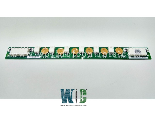
IS200JPDLG1AAB - Local Pack DC Power Distribution Board is available in stock which ships the same day.
IS200JPDLG1AAB - Local Pack DC Power Distribution Board comes in UNUSED as well as REBUILT condition.
To avail our best deals for IS200JPDLG1AAB - Local Pack DC Power Distribution Board, contact us and we will get back to you within 24 hours.
SPECIFICATIONS:
Part Number: IS200JPDLG1AAB
Manufacturer: General Electric
Series: Mark VIe
Product Type: Local Pack DC Power Distribution Board
Technology: Surface mount
Input Voltage: 28 V DC
Operating temperature: -30 to 65°C
Input Feed Type: Up to 3
Input Connector: 5-pin Mate-N-Lok
Number of Output Circuits: 6
Weight: 2 lbs
Return Current: Common among the three TMR feeds
Size: 33.02 cm high x 10.16 cm
Repair: 3-7 Days
Availability: In Stock
Weight: 2 lbs
Country of Origin: United States
Manual: GEH-6721G
FUNCTIONAL DESCRIPTION:
IS200JPDLG1AAB is a Local Pack DC Power Distribution Board manufactured and designed by General Electric as part of the Mark VIe Series used in GE Distributed Control Systems. The Local Pack DC Power Distribution (JPDL) board provides DC power distribution between the source of control power (possibly JPDP or JPDS) and multiple I/O packs, as well as provides daisy chain-style connections for multiple downstream JPDL boards. Branch circuit protection is provided for each I/O pack connection with positive temperature coefficient fuse devices. The board is designed to make it easy to maintain up to three isolated control power distribution circuits to complement control hardware redundancy. In a TMR system, it will be common to have separate control power for R, S, and T hardware. By providing for three separate power circuits on one board, JPDL allows organized separation of the control power.
INSTALLATION:
The JPDL board is designed for vertical mounting on a metal bracket positioned adjacent to the I/O packs, ensuring compact and organized placement within the control system rack. DC power input cables are connected at the rear of the board, while output cables to the I/O packs and downstream JPDL boards are routed from the front, facilitating easy access for wiring, inspection, and maintenance. This configuration supports efficient power distribution and reduces cable congestion, while maintaining clear separation of control power circuits for redundancy and system reliability. Proper grounding and secure mounting are recommended to ensure optimal performance and minimize electrical noise or interference.
Mounting the Board: Secure the JPDL board vertically on a metal mounting bracket located adjacent to the I/O packs. Ensure the bracket is properly grounded to prevent electrical interference.
OPERATION:
Input power is typically 28 V dc, received from JPDP or JPDS as up to three redundant feeds. The 5-pin Mate-N-Lok input connector receives the three separate power feeds on three different pins for triple redundancy. The feeds are designated Red, Blue, and Black. The JP1, 2, and 3 connectors on JPDP provide this connection. Return current is common among the three TMR feeds and is passed on the remaining two pins of the 5-pin Mate-N-Lok connector. Six identical output circuits provide power feeds to individual I/O packs. Two are sourced from each of the R, S, and T feeds (red, blue, and black). Each of the six I/O pack feeds includes a resetting positive temperature coefficient fuse device, labeled CL (current limit), to provide branch circuit protection that is coordinated with the wire between JPDL and the I/O pack.
WOC maintains the largest inventory of OEM replacement parts for GE Distributed Control Systems (DCS), offering new, unused components as well as professionally rebuilt and fully warranted boards. In addition, we provide expert repair services for faulty or damaged boards, restoring them to full operational capability. Our team of specialists is available 24/7 to support all OEM requirements, offering prompt technical guidance, system compatibility advice, and solutions for any automation need. For pricing, availability, or assistance with parts and repairs, contact our team via phone or email to ensure your systems continue to operate reliably and efficiently.
What type of connector is used for the input power connection?
A 5-pin Mate-N-Lok connector is used for the DC power input. Three pins are allocated for the R, S, and T feeds, while the remaining two are used for the common return current path.
How many isolated control power circuits are supported on the board?
The board supports three isolated control power circuits, one for each redundant feed (R, S, and T). This separation allows independent control power for each channel, enhancing fault isolation and system reliability.
How many output circuits are provided, and how are they distributed across R, S, and T feeds?
The JPDL board provides six identical output circuits, with two outputs sourced from each R, S, and T input feed. This allows balanced distribution of power across multiple I/O packs.