World Of Controls understands the criticality of your requirement and works towards reducing the lead time as much as possible.
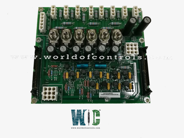
IS200JPDBG2ABB - AC Power Distribution Module is available in stock which ships the same day.
IS200JPDBG2ABB - AC Power Distribution Module comes in UNUSED as well as REBUILT condition.
To avail our best deals for IS200JPDBG2ABB - AC Power Distribution Module, contact us and we will get back to you within 24 hours.
SPECIFICATIONS:
Part Number: IS200JPDBG2ABB
Manufacturer: General Electric
Series: Mark VIe
Product Type: AC Power Distribution Module
Board Rating: 115/230 V ac
Memory: 128 MB SDRAM
Operating system: QNX
Programming: Boolean
Voltage Range: 14 to 32 V dc
Maximum Lead Resistance: 15 Ohm
Operating temperature: 0 to 70 Deg C
Technology: Surface mount
Size: 16.2 cm high x 8.6 cm
Repair: 3-7 Day
Availability: In Stock
Weight: 2 lbs
Country of Origin: United States
Manual: GEH-6421D
FUNCTIONAL DESCRIPTION:
IS200JPDBG2ABB is an AC Power Distribution Module manufactured and designed by General Electric as part of the Mark VIe Series used in GE Distributed Control Systems. The AC Power Distribution Module conditions, monitors, and distributes AC power. It includes two line filters and an IS200JPDB circuit board. The module supports two independent AC distribution circuits, each rated at 20 A for 115 or 230 V AC. To avoid PPDA alarms when using a single AC power source, the input circuits must be wired in parallel. Each circuit offers one fused and three fused-and-switched branch circuit outputs. The module allows connection to an optional JPDF 125 V DC distribution module. The IS200JPDB features passive monitoring circuits for AC magnitudes and provides status feedback for all fused circuits. Monitoring circuits are accessible via connector P1, which supports a cable connection to a power diagnostic PPDA I/O pack. Additionally, the P2 connector facilitates the pass-through of monitoring signals from other power distribution system cards.
OPERATION:
Mark VIe systems distinguish between a protective earth (PE) and a functional earth (FE). The PE ground must be connected to an appropriate earth point following local standards, with a minimum capacity to carry 60 A for 60 seconds and a voltage drop not exceeding 10 volts. The FE ground must be bonded to the PE ground at a single point.
The JPDB module is grounded through its metal mounting supports, which are secured to the underlying sheet metal of the module. This ground connection extends to the metal switch bodies on the JPDB and serves as a local reference for feedback signals on P2. The module’s sheet metal is insulated from the mounting surface to allow its ground to remain independent of the mounting base.
Typically, the JPDB is installed on a backplate grounded to FE, positioned low in the cabinet. A separate ground wire connects the JPDB to PE. This wire's length must be minimized to reduce impedance at radio frequencies, ensuring proper operation of the input line filters.
INSTALLATION:
The IS2020JPDB module is mounted vertically on a metal backplate within the PDM cabinet. A connection must link the module’s sheet metal to the system's Protective Earth. Input power is supplied to terminals AC1H (line) and AC1N (neutral) for the first AC circuit, and AC2H (line) and AC2N (neutral) for the second, with both requiring grounded neutral connections. Output circuits should follow the system documentation for proper connections. If a PPDA power diagnostic I/O pack is part of the power distribution system, a 50-pin ribbon cable connects JPDB connector P1 to the P2 connector on the PPDA board. This connection can pass through other PDM core boards via their P2 connectors if necessary.
I/O CHARACTERISTICS:
WOC has the largest stock of OEM Replacement Parts for GE Distributed Turbine Control Systems. We can also repair your faulty boards and supply unused and rebuilt boards backed up with a warranty. Our team of experts is available round the clock to support your OEM needs. Our team of experts at WOC is happy to assist you with any of your automation requirements. For pricing and availability on parts and repairs, kindly contact our team by phone or email.
What is the maximum rating for the AC input terminals on the JPDB module?
The AC input terminals on the JPDB module are rated at 20 A RMS. Branch circuit protection should be no larger than a 30 A circuit breaker. The circuits are rated for 115/230 V AC and 20 A for each of the two circuits feeding JAF1.
How do I connect the AC power to the JPDB module?
Power is connected via a nine-position Mate-N-Lok connector, J1, which accepts power from line filters. Dual pins are used for each connection to support the current rating. The wire harness is part of the module, and wiring diagrams should be referred to for proper hookup.
What is the purpose of the wire harness provided with J1?
The wire harness that comes with J1 is designed to connect the power inputs to the JPDB board and support the current rating, ensuring proper power delivery.