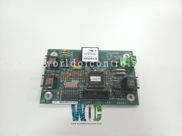
IS200ISBDG1A - Insync Delay Board

IS200ISBDG1A - Insync Delay Board IS200ISBDG1A - Insync Delay Board

World Of Controls understands the criticality of your requirement and works towards reducing the lead time as much as possible.

IS200ISBDG1A - Insync Delay Board is available in stock which ships the same day.

IS200ISBDG1A - Insync Delay Board comes in UNUSED as well as REBUILT condition.

To avail our best deals for IS200ISBDG1A - Insync Delay Board, contact us and we will get back to you within 24 hours.

SPECIFICATIONS

Part Number: IS200ISBDG1A
Manufacturer: General Electric
Series: EX2100
Product Type: Insync Delay Board
Repair: 3-5 days
Availability: In Stock
Country of Manufacturer: United States (USA)

Functional Description

IS200ISBDG1A is an Insync Delay Board developed by General Electric. It is a part of the EX2100 excitation system. It is an Insync Delay Board, featuring terminal connections, connectors for connections, and integrated circuits. It also incorporates LEDs, test points, and other components to ensure precise and efficient operation within the power generation landscape.

Features

  • It is drilled in two corners, and each corner features a terminal connection labeled as E1, E2, E3, and E4. These terminals serve as key points for electrical connections and signal transfers. In addition to these corner terminals, the board incorporates five more connectors, each positioned on the board's edges.
  • These connectors include a male vertical pin ribbon connector (P5), a two-position terminal strip (P4) clearly labeled as '24 VDC Input,' and three additional connectors, namely P1 ('Full Duplex'), P2 ('XMIT Out'), and P3 ('RCV In'). These connectors play a pivotal role in establishing electrical connections and ensuring the seamless operation within the Mark VI system.
  • Includes a DATEL dc/dc converter component, which is instrumental in transforming and regulating electrical power as required. These integrated circuits are the essential building blocks of the board's operation.
  • For monitoring and diagnostics, the board features two light-emitting diodes (LEDs) with distinct labels. One is identified as 'carrier detect,' while the other is marked as 'power.'
  • These LEDs provide visual cues to indicate the status of critical functions.
  • It incorporates TP test points, which are invaluable for conducting tests and inspections to ensure its proper functioning.

System Hardware Overview

  • The control cabinet is the central hub for the EX2100 system, housing critical components responsible for control, communication, and input/output (I/O) operations. This cabinet serves as the brain of the system, orchestrating and supervising various functions essential for the excitation process.
  • Within the control cabinet, a range of boards play a pivotal role in regulating and monitoring the power generation process. These boards are equipped with advanced control circuitry that ensures precise control over the exciter's performance. They also facilitate seamless communication with other system components and external devices.
  • The auxiliary cabinet is tasked with safeguarding power generation through a series of protection circuits and field flashing mechanisms. One of its primary functions is to handle de-excitation, which is essential for safely shutting down the excitation system when required. Additionally, the auxiliary cabinet incorporates circuits designed to suppress shaft voltage, protecting the integrity of the power generation equipment.
  • This cabinet is a guardian of power generation, ensuring that the system operates reliably and safely even under challenging conditions or when specific interventions are necessary.
  • The power conversion cabinet houses the heart of the electrical transformation process within the EX2100 system. It is equipped with a range of components designed to convert and regulate electrical power to meet the system's requirements. The central element in this cabinet is the power SCR (Silicon-Controlled Rectifier) cells, which play a pivotal role in controlling the flow of electricity.
  • Cooling fans are incorporated to maintain optimal operating temperatures, ensuring the SCR cells operate efficiently. Additionally, the power conversion cabinet contains direct current (DC) contactors and alternating current (AC) disconnect mechanisms, which are instrumental in controlling and managing the power output.
  • At the core of the power conversion process is the power converter. This component consists of bridge rectifiers, resistor/capacitor filter configurations, and control circuitry. The bridge rectifiers are key in converting alternating current (AC) into direct current (DC), a fundamental step in the excitation process.

Board Handling Precautions

  • Static Electricity Prevention: Static-sensitive handling techniques must be employed to prevent component damage due to static electricity. This involves using proper grounding methods.
  • Wrist Grounding Strap Usage: When handling boards or components, wearing a wrist grounding strap is essential. However, this should only be done after the boards or components have been removed from potentially energized equipment and are in a normally grounded workstation.
  • Packaging for Shipment: GE ships replacement boards in anti-static bags to ensure protection during transit. These bags are specifically designed to mitigate the risk of static-related damage.
  • Guidelines for Handling Boards: Adherence to specific guidelines is crucial when handling boards:
    • Storage in Anti-Static Bags/Boxes: Boards should be stored in anti-static bags or boxes to maintain a static-safe environment, preventing any discharge that might harm the components.
    • Grounding Strap Usage: Utilize a grounding strap while handling boards or their components, as previously mentioned in the caution criteria. This ensures a continuous path for static electricity to dissipate, safeguarding the components.

WOC has the largest stock of Speedtronic control spares. Please contact our staff by phone or email for pricing and availability on any parts and repairs


FREQUENTLY ASKED QUESTIONS

What is IS200ISBDG1A?
It is an insync Delay Board developed by General Electrics.

What is the role of the control cabinet in the EX2100 system?
The control cabinet is the central hub of the EX2100 system, responsible for control, communication, and input/output operations. It serves as the brain of the system, orchestrating and supervising essential functions for power generation.

What components are housed within the control cabinet, and what is their function?
The control cabinet contains a range of boards with advanced control circuitry that regulates and monitors the power generation process. These boards ensure precise control of the exciter's performance and facilitate seamless communication with other system components and external devices.

What is the primary role of the auxiliary cabinet in the EX2100 system?
The auxiliary cabinet is dedicated to safeguarding power generation. It includes protection circuits and field flashing mechanisms. One of its key functions is handling de-excitation, which is crucial for safely shutting down the excitation system when needed. Additionally, it incorporates circuits designed to suppress shaft voltage, thus protecting the power generation equipment's integrity.