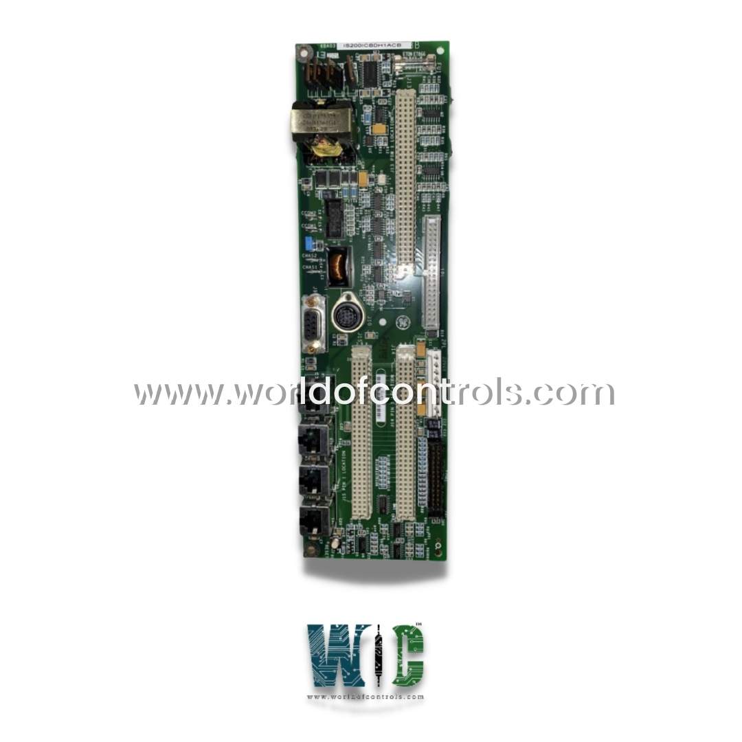
SPECIFICATIONS
Part Number: IS200ICBDH1A
Manufacturer: General Electric
Series: EX2100
Function: Control Base Card
Ethernet jacks: J12A, J12B, J11A, and J11B
Connectors: CHAS 1, CHAS2, CCOM 2, and CCOM1
Manual: GEH-6632
Repair: 3-5 Days
Product type: PCB
Availability: In Stock
Country of Manufacture: United States (USA)
Functional Description
IS200ICBDH1A is a Control Base Card developed by GE. It is a part of EX2100 excitation system. The GE Energy EX2100 Excitation Control System is a cutting-edge platform for generator excitation. This control card is specifically designed to enhance the functionality and performance of the excitation system, ensuring reliable and efficient operation of generator excitation processes. The excitation Control System is an advanced and sophisticated platform used for controlling and regulating generator excitation. In addition to the Control Base Card, the excitation system comprises various components such as transformers, multiple controllers, power bridges, and a protection module. This comprehensive system is engineered to deliver optimal performance and precise control over generator excitation.
IS200ICBDH1A Features
Versatile Connectivity
- The control card offers a range of inputs and outputs designed to enable seamless integration and enhance operational efficiency.
Jack Connectors for External Devices
- Notably, the card includes four jack connectors, specifically J11A, J11B, J12A, and J12B, along one edge.
- These connectors provide convenient points for connecting external devices and components.
Flexible Interface Options
- The board is equipped with two female connectors: J9, a 9-pin D-sub connector, and J10, an 8-pin mini-DIN connector.
- These connectors offer flexibility for interfacing with various equipment, facilitating effective communication and data exchange.
Secure Backplane Connectivity
- The Control Base Card features three female backplane connectors, each labeled Pin 1.
- These connectors ensure secure and reliable connections to the backplane, facilitating efficient data and signal transmission between the control card and other system components.
Robust Physical Connectivity
- In terms of physical connectivity, the board incorporates four stab-on connectors and four vertical male pin connectors.
- These connectors establish robust and reliable connections to external devices, enhancing the overall stability and integrity of the control system.
Seamless Integration
- The GE EX2100 excitation system offers advanced functionalities for generator excitation.
- This comprehensive system includes multiple controllers, power bridges, a protection module, and transformers. Its integrated design allows seamless integration with various components, such as turbine controls, static starters, distributed control systems, and human-machine interfaces (HMI).
Elimination of Third-Party Interfaces
- Eliminates the need for third-party interfaces or gateways, simplifying the integration process.
- This feature enables efficient communication and coordination among different system elements.
Ethernet Local Area Network (LAN) Communication
- The system architecture relies on Ethernet Local Area Network (LAN) communication, known as the Unit Data Highway.
- This communication protocol enables interaction and data exchange with other GE equipment, including the GE Control System Toolbox (toolbox) for configuration, the turbine control system, the Load Commutated Inverter (LCI) Static Starter, and the operator interface (HMI).
- Seamless integration and communication within the network enhance control, monitoring, and operation of the generator excitation process.
Stab-On Connections and Mounting
- The board features 4 stab-on connections, meticulously labeled as CCOM1, CCOM2, CHAS2, and CHAS1.
- Strategic factory-drilled holes positioned at the corners facilitate efficient mounting of the board. Furthermore, the presence of two terminal screws allows seamless wiring connections.
Redundant Control System
In a redundant control system, reliability and fault tolerance are prioritized by incorporating multiple controllers and redundant power supplies. Here are the key components and features of a redundant control system:
- Controllers: The redundant control system comprises three controllers, denoted as Controller A, Controller B, and Controller C. These controllers are responsible for executing the control algorithms, monitoring system parameters, and ensuring the safe and efficient operation of the overall system. Each controller is equipped with its own processing unit, memory, and input/output interfaces.
- Redundant Power Supplies: To ensure uninterrupted power and mitigate the risk of power supply failures, the redundant control system incorporates three independent power supplies. Each controller is connected to a dedicated power supply, providing a reliable power source for continuous operation. This redundancy ensures that even if one power supply malfunctions, the other two power supplies can sustain the controllers' power requirements.
- Ground Detector Modules: In the power supply rack, three ground detector modules are installed. These modules play a vital role in detecting ground faults in the system. By continuously monitoring the grounding status, these modules provide an additional layer of safety by quickly identifying and alerting the controllers to any potential ground faults.
- Redundant Communication: To establish redundant communication links with the turbine control system and Human Machine Interfaces (HMIs), up to two Ethernet cables are connected to the ACLA controllers. These Ethernet connections provide reliable and redundant communication channels for data exchange, control commands, and system monitoring. Each controller, represented by two keypads labeled M1 and M2, can independently interface with the turbine control system and HMIs. Controller C acts as a central hub, making the information accessible to both keypads.
By incorporating redundant controllers, power supplies, and communication channels, the redundant control system enhances system reliability and fault tolerance. In the event of a controller or power supply failure, the system can seamlessly switch to the redundant components, minimizing downtime and ensuring continuous operation. The redundancy also allows for concurrent monitoring and control through multiple keypads, providing flexibility and ease of operation.
Control System Toolbox
The Control System Toolbox plays a crucial role in configuring, maintaining, and monitoring the exciter system. With its comprehensive set of features and user-friendly interface, the toolbox empowers operators and maintenance personnel to effectively manage and optimize the exciter's performance. Here are the key aspects and functionalities of the Control System Toolbox:
- Configuration and Loading of Control Blocks and Diagrams: The toolbox provides a platform for configuring and loading control blocks and diagrams into the exciter's control system. These control blocks and diagrams define the specific control algorithms, parameters, and logic that govern the excitation process. By customizing and fine-tuning these configurations, operators can tailor the exciter's behavior to meet the requirements of the power generation system.
- Real-time Data Display: Upon turning on the exciter system, the toolbox screen displays real-time data, allowing operators to monitor critical variables and performance parameters. This real-time data includes information on excitation levels, voltage and current measurements, system status, and other relevant diagnostics. The ability to observe this data in real-time enables operators to assess the exciter's behavior, identify any anomalies, and make informed decisions to ensure optimal system performance.
- Control System Diagnostics: The toolbox provides built-in control system diagnostics that assist in troubleshooting and identifying potential issues within the exciter system. These diagnostics may include alarms, error codes, warning indicators, or graphical representations of system health. By analyzing these diagnostics, maintenance personnel can pinpoint the root cause of any malfunction or abnormal behavior, facilitating efficient troubleshooting and timely resolution of issues.
- Software Deployment and Connectivity Options: The toolbox software can be deployed on either the UDH's (User Display and HMI) server or a separate PC, providing flexibility in system setup. This allows operators and maintenance personnel to access the toolbox from their preferred workstation, enhancing convenience and accessibility.
System De-Excitation
- System de-excitation is a crucial process during generator shutdown to dissipate the stored energy in the generator field inductance. In the EX2100 exciter, the de-excitation module, along with a field discharge resistor or inductor, is responsible for this energy dissipation. The de-excitation module ensures a controlled and safe de-energization of the generator's field.
- In standard de-excitation mode, a freewheeling diode is employed to provide the necessary de-excitation functionality. However, for higher performance applications, an enhanced de-excitation module is utilized. This module comprises a thyristor, available in either a 53 mm or 77 mm cell size, which is mounted on a large heatsink assembly. The thyristor is accompanied by an attached snubber network, which helps manage switching transients and improve overall performance.
- To monitor and control the de-excitation process, the de-excitation module incorporates hall effect conduction sensors. These sensors are strategically installed in the air gap of a circular steel core, which is attached to the board. The hall effect sensors detect the magnetic field generated by the thyristor's field discharge current. This information is then utilized to regulate the de-excitation process effectively.
- The de-excitation module employs two separate sensor circuits. Each circuit operates independently, ensuring redundancy and enhancing the reliability of the de-excitation system. These circuits are powered by separate power supplies and utilize separate conduction sensors. The dual circuits enable the de-excitation module to react to the control inputs, firing the thyristor when one of the two control inputs becomes true or when the anode-to-cathode voltage of the thyristor surpasses a specific threshold. This redundancy and independent operation contribute to the overall robustness and safety of the de-excitation system.
- By employing the de-excitation module and utilizing hall effect conduction sensors, the system ensures controlled dissipation of the generator field's stored energy during shutdown. The integration of separate sensor circuits and redundant control mechanisms enhances reliability and provides effective protection during the de-excitation process, thereby safeguarding the generator and its associated components.
System UDH Communicator
- Communication between controllers is orchestrated through the UDH (Universal Data Highway). A UDH communicator is specifically chosen from the controllers to facilitate the transmission of panel data within the network. This data encompasses crucial elements, encompassing control signals (EGD) and alarm notifications.
- Data Transmission and Controller Independence: Every controller establishes an autonomous, physical link with the UDH. This individual connection enables seamless data transmission across the network. Even in scenarios where the UDH network encounters disruptions, each controller retains its connection to the UDH.
- Controller Resilience and UDH Communication: In cases of UDH network fragmentation, where a fracture isolates a controller from its fellow counterparts, the affected controller steps into a pivotal role. It assumes the mantle of the UDH communicator for that specific fragmented network. This transition ensures that communication channels are maintained within the fragmented portion of the UDH.
- Designation and Multiplicity of UDH Communicators: Within the context of a single panel, a designated controller is nominated to fulfill the role of UDH communicator. However, the network accommodates the possibility of multiple UDH communicators. Notably, the designated controller always fulfills the role of the UDH communicator, ensuring efficient communication across the network's expanse.
Components
- 1 fuse
- 1 RS-232 9-pin port
- 1 circular 8-pin female port
- 1 black 40-pin connection
- 1 black 10-pin connection
- 1 26-pin black connection
- 1 white 9-pin male port
- 3 white 96-pin female ports
- Other - 10 diodes, 61 capacitors, 95 resistors, 3 transformers, 15 integrated circuits, 1 inductor coil
Ethernet Jacks
Connectors
Mounting Features
- Factory drilled holes on the four corners for mounting purposes
- Two terminal screws for wiring connections
WOC is happy to assist you with any of your automation requirements. Please contact us by phone or email for pricing and availability on any parts and repairs.
FREQUENTLY ASKED QUESTIONS
What is IS200ICBDH1A?
It is a Control Base Card developed by GE
What is the primary function of the board?
The primary function of the ICBD is to connect the basic input and output to the exciter within the control system and handle the majority of the EX2100e system I/O interfaces.
What are the types of inputs and outputs available on the board?
It has a variety of inputs and outputs, including four jack connectors (J11A, J11B, J12A, and J12B), two female backplane connectors, four stab-on connectors, and four vertical male pin connectors.
What is the exciter toolbox?
It is a software tool used to configure and maintain the exciter.
What can be configured and loaded into the control system using the toolbox?
Control blocks and diagrams can be configured and loaded into the control system using the toolbox.