SPECIFICATIONS
Part No.: IS200ERIOH1ACB
Manufacturer: General Electric
Country of Manufacture: United States of America (USA)
Temperature: 0 to 60 °C
Product Type: Exciter Regulator Main I/O Board
Availability: In Stock
Series: EX2100
Functional Description
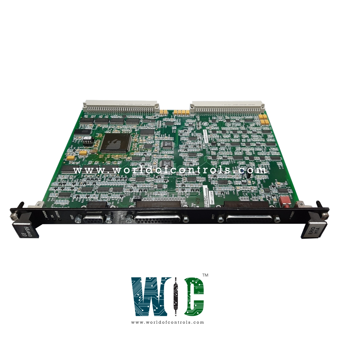
IS200ERIOH1ACB is an Exciter Regulator Main I/O Board developed by GE. It is a part of EX2100 excitation system. Exciter Regulator Main I/O Board serves as a pivotal component within the EX2100 regulator control systems, catering to both simplex and redundant applications. Designed to provide a versatile Input/Output (I/O) interface, the board plays a crucial role in facilitating communication between customer I/O signals and various system components, contributing to the seamless operation of the excitation control system.
Functionality in Simplex Applications
- In simplex configurations, the ERIO board is securely mounted in the Exciter Regulator Backplane (ERBP). It acts as the interface hub for customer I/O signals originating from the Exciter PT/CT Terminal Board (EPCT) and the Exciter Contact Terminal Board (ECTBG2).
- Additionally, the board interfaces with system I/O signals for the Exciter Regulator Dynamic Discharge board (ERDD) and the Exciter Regulator Options Card (EROC), contributing to the overall functionality of the simplex excitation control system.
Role in Redundant Applications
- In redundant setups, the board is mounted not only in the ERBP (M1) but also in the Exciter Regulator Redundant Backplane (ERRB, M2/C). This dual-mounting ensures redundancy and fault tolerance in the excitation control system.
- The board, in redundant configurations, interfaces customer I/O signals for the Exciter PT/CT Terminal Board and the Exciter Contact Terminal Board. Simultaneously, it handles system I/O signals for the ERDD, EROC, and the Exciter Regulator Redundant Relay board (ERRR).
Key Interface Points
- Serving as a central hub, the board facilitates the exchange of information between customer and system I/O signals.
- Customer I/O signals consist of inputs and outputs customized to specific excitation system requirements.
- System I/O signals include crucial communication pathways essential for dynamic discharge, option management, and redundant relay functionalities within the exciter.
Importance of Redundancy
- The strategic placement of the board within both the Excitation Regulator Baseplate (ERBP) and the Excitation Regulator Rear Base (ERRB) (M2/C) bolsters system resilience.
- In the event of a board failure, redundancy ensures uninterrupted operation, thereby fortifying system reliability and mitigating potential disruptions.
Contribution to System Integration
- Versatility in managing diverse I/O signals, whether in simplex or redundant configurations, underscores its crucial role in facilitating effective communication and integration within EX2100 regulator control systems.
- By fostering seamless interaction between components, the board significantly enhances the reliability, safety, and overall performance of the excitation control system.
Indicator LEDs
- POWER LED: Serves as an immediate visual cue indicating the application of power to the ERIO board. When illuminated, it confirms that the board is receiving power, signifying the initiation of the operational state. This indication is crucial during system startup and power application procedures, allowing operators to verify the power supply to the ERIO board.
- OK LED: Designed to convey the overall health and functionality of the ERIO board. When illuminated, it signifies that the board is operating correctly without any detected faults or malfunctions. The OK LED provides a quick and convenient visual check for operators, reassuring them that the ERIO board is functioning as expected. In the absence of illumination, it could indicate potential issues that require attention or further investigation.
- ACTIVE LED:Assumes significance in scenarios where redundancy is implemented, and the control system designates one of the ERIO boards as the master controller. This LED illuminates to indicate that the specific ERIO board is actively selected as the master controller within the redundant setup. The ACTIVE LED serves as a real-time indicator of the board's role in the control system hierarchy, providing crucial information on its status in relation to redundancy.
The WOC team is always available to help you with your EX2100 requirements. For more information, please contact WOC.
Frequently Asked Questions
What is IS200ERIOH1ACB?
It is an Exciter Regulator Main I/O Board developed by GE under the EX2100 series.
What is the main function of the Exciter Regulator Main I/O Board?
The board serves as the Input/Output interface for customer and system connections in the EX2100 regulator control systems, facilitating communication and signal exchange.
What are the key indicator LEDs on the board, and what do they signify?
The board features three green LEDs - POWER (indicating applied power), OK (confirming correct functionality), and ACTIVE (signifying selection as the master controller in redundant setups).
Can the board be used for permanent customer connections?
No, it is not intended for permanent customer connections. It is specifically designed for interfacing with test equipment, such as oscilloscopes or chart recorders.
