World Of Controls understands the criticality of your requirement and works towards reducing the lead time as much as possible.
IS200EPDMG1ABA - Exciter Power Distribution Module is available in stock which ships the same day.
IS200EPDMG1ABA - Exciter Power Distribution Module comes in UNUSED as well as REBUILT condition.
To avail our best deals for IS200EPDMG1ABA - Exciter Power Distribution Module, contact us and we will get back to you within 24 hours.
SPECIFICATIONS:
Part Number: IS200EPDMG1ABA
Manufacturer: General Electric
Series: EX2100
Product Type: Exciter Power Distribution Module
Number of channels: 12
Input span: 4-20 mA
Technology: Surface Mount
Common Mode Voltage Range: ±5 V
Maximum Lead Resistance: 15Ω
Analog output current: 0-20 mA
Operating temperature: -30 to 65 °C
Size: 8.26 cm high x 4.19 cm
Repair: 3-7 Day
Availability: In Stock
Country of Origin: United States
Manual: GEI-100511
FUNCTIONAL DESCRIPTION:
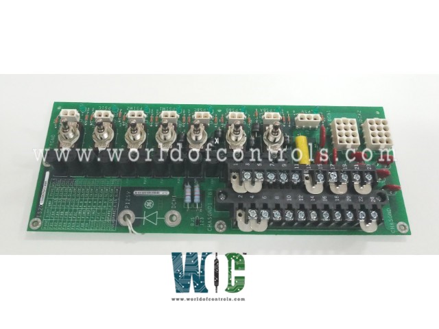
IS200EPDMG1ABA is an Exciter Power Distribution Module manufactured and designed by General Electric as part of the EX2100 Series used in GE Excitation Control Systems. The IS200EPDM Exciter Power Distribution Module (EPDM) is used in the EX2100 Excitation Control to provide power for the control, I/O, and protection boards of the exciter. It is mounted on the side of the IS200EPBP Exciter Power Backplane (EPBP) receives 125 V dc power from the station battery and accepts one or two 120 V ac power inputs for backup. All power supply inputs are received through a board-mounted terminal block (TB1) and are filtered. Each ac supply is rectified to 125 V dc in an external Ac to Dc Converter (DACA). The resulting two or three dc voltages are diode coupled through external diodes to create the dc source power supply, designated P125V and R125V. These voltages are center grounded and are nominally +62.5 V and ñ62.5 V to ground.
The module is chassis-grounded and safety-grounded through four of the board mounting holes. Two 12-plug connectors (JDACA1 and JDACA2) connect the ac power sources from the terminal block (AC1 and AC2) to the external DACA#1 and DACA#2 and return the DACA outputs to the 125 V dc lines (P125 and R125). Individual power supply outputs to each of the exciter boards are fused, have an on/off toggle switch (except the EXTB board), and a green LED indicator to show power availability. The outputs supply up to three IS200EGPA Exciter Gate Pulse Amplifier Boards (EGPA), the IS200EXTB Exciter Terminal Board (EXTB), and three IS200EPSM Exciter Power Supply Modules (EPSM) serving three controllers. A separate connector is provided for each output and these are wired to the EPBP for distribution.
APPLICATION DATA:
The EPDM module includes a 24-point terminal block, ten plug connectors, seven switches, fourteen fuses, four grounded mounting holes, eight LED indicators, and one adjustable jumper. All connectors are rated 600 V ac or dc. The terminal board is rated 300 V (10 A per pin); all switches are rated 125 V dc, 6 A. The adjustable jumper (BJS) is for isolation of ground reference on systems with external reference. An Exciter Power Distribution Module is a critical component in electrical power systems, particularly in power plants and large industrial applications. It plays a key role in regulating and distributing power to ensure the stable operation of generators and other machinery. Here are some notable features of an Exciter Power Distribution Module:
WOC has the largest stock of GE Excitation Control System Replacement Parts. We can also supply unused and rebuilt backed-up with a warranty. Our team of experts is available round the clock to support your OEM needs. Our team of experts at WOC is happy to assist you with any of your automation requirements. For pricing and availability on any parts and repairs, kindly contact our team by phone or email.
What is an Exciter Power Distribution Module?
An Exciter Power Distribution Module is a device used in electrical power systems to regulate and distribute power to the generator's exciter, which is responsible for providing the necessary field current to the generator's rotor.
Why is an Exciter Power Distribution Module important?
This module is critical for maintaining stable voltage levels in the generator, ensuring reliable and efficient operation of the power system. It helps prevent voltage fluctuations, which can lead to equipment damage or power outages.
How does an Exciter Power Distribution Module work?
The module regulates the voltage applied to the generator's field winding by adjusting the exciter current. It uses automatic voltage regulators (AVRs) to monitor and control the output voltage, maintaining stability despite load changes
.