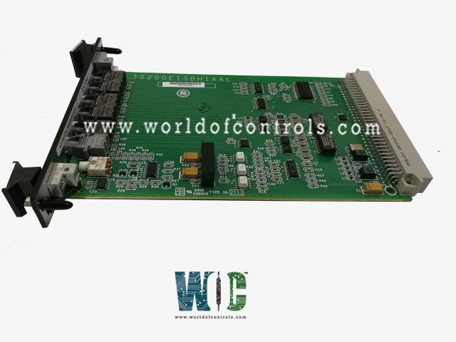
IS200EISBH1AAB - Exciter ISBus Board

IS200EISBH1AAB - Exciter ISBus Board IS200EISBH1AAB - Exciter ISBus Board

World Of Controls understands the criticality of your requirement and works towards reducing the lead time as much as possible.

IS200EISBH1AAB - Exciter ISBus Board is available in stock which ships the same day.

IS200EISBH1AAB - Exciter ISBus Board comes in UNUSED as well as REBUILT condition.

To avail our best deals for IS200EISBH1AAB - Exciter ISBus Board, contact us and we will get back to you within 24 hours.

SPECIFICATIONS

Part No.: IS200EISBH1AAB
Manufacturer: General Electric
Country of Manufacture: United States of America (USA)
Size: 33.02 cm high x 17.8 cm wide
Technology: Surface-mount
Product Type: Exciter ISBus Board
Availability: In Stock
Series: EX2100

Functional Description

IS200EISBH1AAB is an Exciter ISBus Board developed by GE. It is part of EX2100 series. Exciter ISBus Board is a specialized communication board tailored explicitly for the M1, M2, and C controllers within the context of generator control systems. Its primary function involves receiving and transmitting fiber-optic feedback signals, subsequently transmitting these signals over the control backplane to the DSPX controller. Additionally, the EISB board facilitates communication between the DSPX and the tool and keypad ports using RS-232C, accomplished through the backbone connector.

Key Functions and Interfaces

  • Fiber-Optic Signal Transmission: Serves as a conduit for receiving and transmitting fiber-optic feedback signals from the generator field and the Exciter (if required). This communication is facilitated using EDCF boards and is pivotal for accurate data transmission within the system.
  • DSPX Communication: Scts as an intermediary, ensuring seamless communication between the DSPX controller and other modules by relaying critical signals and information across the control backplane.
  • Tool and Keypad Ports: Using RS-232C, the board facilitates communication between the DSPX controller and tool/keypad ports. This connectivity enables interaction and data exchange, enhancing the control and monitoring capabilities of the system.
  • Redundant Exciter Support: For redundant exciter setups, the board includes ISBus interface electronics. ISBus, a proprietary GE communications interface, plays a crucial role in transferring data among the M1, M2, and C controllers of the exciter, ensuring redundancy and reliability in communication.

Physical Configuration

  • Form Factor: The module is a single-slot, 3U-high module positioned within the control rack beneath the DSPX controller.
  • Front Panel Connectivity: The front panel of the board accommodates fiber-optic connectors for accepting current and voltage signals from the generator field and the Exciter. It also serves as the point for receiving and transmitting signals to the ground detection module.

Keypad and Tool

  • The EISB (Exciter ISBus Board) incorporates specialized RS-232C drivers to facilitate communication with both the keypad and an external computer via the tool port. These RS-232C drivers serve as interfaces, enabling data exchange and control between the EISB and external devices.
  • RS-232C Driver for Keypad: The EISB board features an RS-232C driver specifically designed to establish communication with the system's keypad.
  • Power Source: It provides a power source for the keypad, offering both +24 V dc and 24 V dc return through the backplane. This power provision ensures that the keypad has the necessary power supply for its operation.
  • Tool Port Communication:RS-232C Driver for External Computer: Similarly, the EISB board incorporates an RS-232C driver dedicated to communication with an external computer through the tool port.
  • Data Rate Flexibility: Communication through the tool port supports a range of data rates, spanning from 1200 to 38.4 KBaud. This flexibility in data rates allows for communication at varying speeds based on system requirements and compatibility with external devices or computers.
  • Data Exchange: The RS-232C drivers facilitate bidirectional data exchange between the EISB and both the keypad and external computer. This communication enables control commands, data transfer, and system monitoring functionalities.
  • Control and Configuration: The keypad communication allows for system control and configuration settings, while the tool port communication with an external computer facilitates tasks such as data logging, diagnostics, and configuration adjustments using dedicated software tools.
    By integrating dedicated RS-232C drivers for keypad and tool port communication, the EISB ensures seamless connectivity and data exchange between the exciter system and external devices. This functionality enables control, configuration, data transfer, and system monitoring, contributing to the overall functionality and efficiency of the exciter system. The provision of power for the keypad further enhances its operational reliability and functionality within the system.

Optical Connectors

Optical connectors play a crucial role in facilitating communication and data transmission between different components within a system, particularly in scenarios where electrical isolation is necessary. 

  • Purpose of Fiber Optic Transmission: Fiber optic transmission serves as a means of communication that offers complete electrical isolation between the EISB and high voltage measurement boards. This isolation is essential for ensuring safety and preventing electrical interference or damage that could occur in high voltage environments.
  • Configuration of Optical Connectors: The optical connectors are designed to accommodate fiber optic cables, which transmit data using light signals rather than electrical signals. These connectors are located on the front panel of the system, providing convenient access for installation and maintenance purposes.
  • Grouping of Optical Receivers: The optical receivers are arranged in two groups on the front panel. In the lower part of the panel, there is a two-piece group consisting of one optical receiver and one transmitter. This grouping allows for efficient and organized connections between the EISB and the high voltage measurement boards.
  • Functionality and Placement: The optical receivers serve to receive data transmitted from the high voltage measurement boards, while the transmitters send data. By utilizing fiber optic technology, these connectors ensure reliable and high-speed data transmission while maintaining electrical isolation.
  • Importance of Electrical Isolation: Electrical isolation is critical in high voltage environments to prevent potential safety hazards such as electrical shocks or equipment damage. Fiber optic transmission provides a secure and reliable method of communication that eliminates the risk of electrical interference or grounding issues.

The WOC team is always available to help you with your EX2100 requirements. For more information, please contact WOC.

Frequently Asked Questions

What is IS200EISBH1AAB?
It is an exciter ISBus board developed by GE under the EX2100 series.

Is it possible to replace a failed EISB while the exciter is running in a redundant control system?
Yes, it's possible to replace the failed board without shutting down the exciter, ensuring continuous operation during the replacement process.

Can the exciter continue running with a failed EISB?
In the event of a single-board failure, the system allows the exciter to run using the remaining functional controller. However, a second board failure in another section could result in the exciter shutdown.

What precautions should be taken during the replacement?
Extreme caution is necessary during replacement, as other components like controllers, power supplies, and terminal boards remain energized. Safety protocols must be strictly followed to prevent accidents or system disruptions.

What risks are associated with a second board failure in a redundant setup?
If a second EISB fails while the exciter is running on the remaining controller, it will lead to the exciter shutdown, emphasizing the importance of prompt replacement and maintenance.