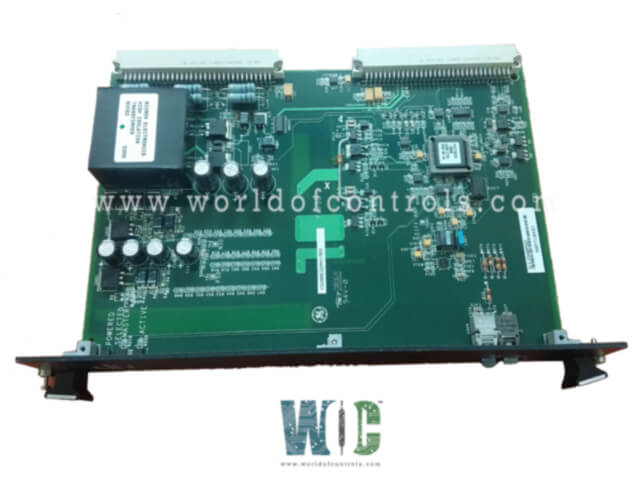
SPECIFICATIONS
Part No.: IS200EGDMH1AGG
Manufacturer: General Electric
Country of Manufacture: United States of America (USA)
Technology: Surface-mount
Temperature Operating: -30 to 65oC
Product Type: Ground Detection Module
Availability: In Stock
Series: EX2100
Functional Description
IS200EGDMH1AGG is a Ground Detection Module developed by GE. It is a part of the EX2100 excitation system. The module serves as an Exciter Ground Detector Module designed to detect field ground leakage current. This module operates alongside an EXAM board to perform its detection function. A simplex system requires one of these modules, while a redundant system utilizes three. The module is capable of detecting field leakage on both the AC and DC sides of the field circuit.
Features
- Form Factor and Mounting: It adopts a space-efficient double-slot, double-height (6U) form factor, ensuring a compact yet powerful design. It is strategically mounted in the Exciter Power Backplane rack (EPBP), emphasizing seamless integration into the overall system architecture.
- Ground Detection Functionality: A core function is to detect field leakage resistance between any point in the generator field circuit and ground. This capability enhances the system's ability to identify potential issues and ensure the overall integrity of the generator field circuit.
- System Configurations: In a simplex system, a single EGDM is utilized, while in a redundant setup, three modules are deployed to bolster reliability. The specific locations are visually represented in Figure 1, providing clarity on their placement within the system.
- Integration with Module: It collaborates with the EXAM, a vital component responsible for sensing voltage across the ground sense resistor. This information is then transmitted to the EGDM(s) through a dedicated nine-conductor cable. The EXAM module finds its physical location within the High Voltage Module situated in the Auxiliary Panel.
- Configuration Control Mechanism: The configuration details for each, including its role as either Controller, Master 1 or Master 2, are dictated by the set of program pins on the P2 connector. This setup facilitates efficient control and coordination, allowing it to perform its designated function within the redundant control architecture.
- Drive Signal Management: Information regarding which master provides the drive signal to the sense resistor in the Attenuator Module is relayed from the DSPX through the EISB (Exciter ISBus Board) in the controller rack to EGDM C. Upon receiving this crucial information over the fiber-optic link, EGDM C takes decisive action. If Master 2 (M2) is identified as the driver, EGDM C activates the relay in the Attenuator Module. Conversely, if Master 1 (M1) is chosen as the master, EGDM C leaves the relay unpowered.
- Differential Signaling and Active Master Selection: Simultaneously, a differential signal is dispatched to Master 1 (M1) and Master 2 (M2), indicating the chosen master for the given operation. This signal serves to enable the signal generator on the active master and selects the test command source on each module (M1, M2, and C). This crucial step ensures synchronized and coherent functionality among the redundant components.
- Oscillator Signal Transmission: Once the active master is identified, it receives an Oscillator Signal over the fiber optic link from the DSPX through the EISB. The master module then adeptly converts this signal into a positive or negative 50-volt square wave voltage. This transformed signal is transmitted via cable to the EXAM (Attenuator Module) and is applied to one end of the Sense Resistor.
LEDs Indicators
- Upper LED - Power Indicator: The uppermost LED serves as a power indicator, conveying information about the board's power status. When illuminated, it signifies that power is successfully applied to the board from the backplane. This indicator offers a quick visual confirmation of the EGDM's operational readiness, ensuring that it is adequately powered to perform its designated functions within the control system.
- Middle LED - Master Selection Indicator: The middle LED is dedicated to indicating the board's role in the redundant configuration. Specifically, when illuminated, it signifies that this board has been selected as the master within the redundant setup. This indication is crucial for operators and maintenance personnel, allowing them to readily identify the board serving as the master in real-time, aiding in troubleshooting and system diagnostics.
- Lower LED - Master Signal Transmission Indicator: The lowermost LED provides information about the master board's active transmission of a 50-volt signal. When illuminated, it indicates that this specific EGDM board is functioning as the master and is actively sending a 50-volt signal. This real-time feedback is instrumental in monitoring the dynamic operation of the master board, ensuring that the necessary signals are being transmitted as per the system requirements.
The WOC team is always available to help you with your EX2100 requirements. For more information, please contact WOC.
Frequently Asked Questions
What is IS200EGDMH1AGG?
It is a Ground Detection Module developed by GE under the EX2100 series.
What is the primary function of the EGDM in the EX2100 Excitation Control system?
It is designed to detect field leakage resistance between any point in the generator field circuit and ground, contributing to the system's integrity monitoring.
How is the EGDM configured in a redundant control setup?
In a redundant control configuration, three boards are designated as Controller (C), Master 1 (M1), and Master 2 (M2). Configuration control is managed by program pins, ensuring streamlined operation.
