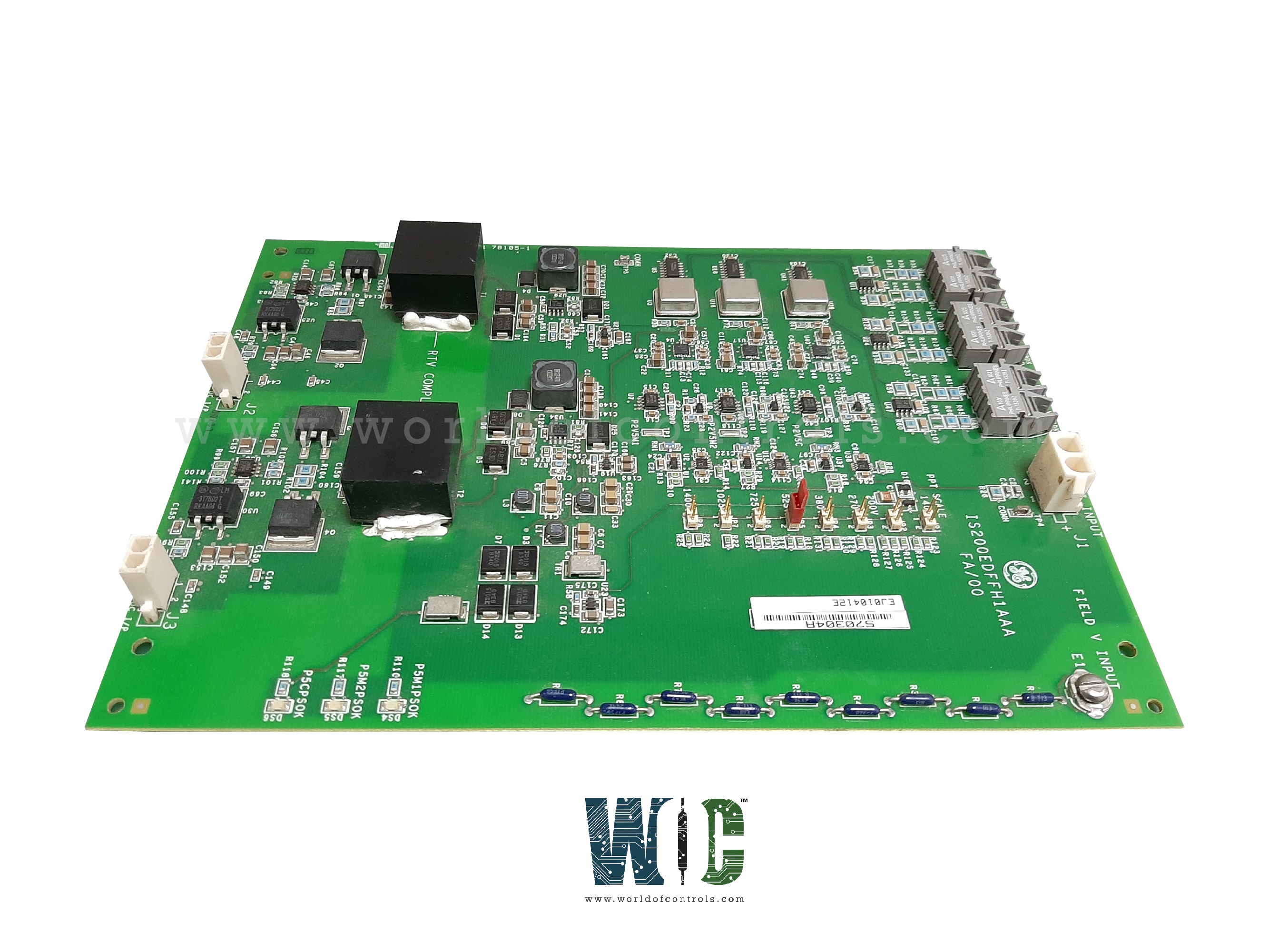
World Of Controls understands the criticality of your requirement and works towards reducing the lead time as much as possible.
IS200EDFFH1A - Exciter DC Fanned Feedback Board is available in stock which ships the same day.
IS200EDFFH1A - Exciter DC Fanned Feedback Board comes in UNUSED as well as REBUILT condition.
To avail our best deals for IS200EDFFH1A - Exciter DC Fanned Feedback Board, contact us and we will get back to you within 24 hours.
SPECIFICATIONS:
Part No.: IS200EDFFH1A
Manufacturer: General Electric
Product Type: Exciter DC Fanned Feedback Board
Group Variation: H2, Dual System
Series: EX2100e
Number of Channels: 13
Description: I/O Terminal Board
AC input frequency: 480 Hz maximum
Ambient temperature: 0 to 40°C
Functionality: Field Current and Voltage Feedback
Number of Selector Settings: 8
Fiber-Optic Link: Voltage Isolation between EAUX and EDFF Boards
High-Noise Immunity: Supported by Fiber-Optic Link
Control Sections: Up to Three Redundant Control Sections
Operating System: Dual System
Availability: In Stock
Country of Manufacture: United States (USA)
FUNCTIONAL DESCRIPTION:
IS200EDFFH1A is an Exciter DC Fanned Feedback Board manufactured and designed by General Electric and is part of the EX2100e Series used in Excitation turbine control systems. The EDFF board measures field current and voltage at the SCR bridge and interfaces to the EX2100e Excitation Control Auxiliary Interface (EAUX) over a high-speed fiber-optic link. The fiber-optic link provides voltage isolation between the two boards, as well as high-noise immunity. Field current is measured using a shunt in the dc field circuit. The field voltage feedback circuit provides eight selector settings to scale the bridge voltage, depending on the bridge application. The EDFF scales and converts the field current and voltage at the exciter or regulator output into frequency feedback signals. It consists of voltage-to-frequency (V-F) converter circuits: one for field current feedback and one for field voltage feedback, for up to three redundant control sections M1, M2, and C.
HIGH VOLTAGE INTERFAC MODULE:
The High Voltage Interface (HVI) module contains the ac line filter fuses and several circuit boards. The Bridge AC Feedback (EBAC) board uses transformers to step down and isolate incoming PPT ac voltage used by the control. The Bridge dc Feedback (EDFF) board uses fiber optics to provide isolated field voltage and current feedback to the control. The EXAM interfaces the field ground detector. All of these boards connect to the EAUX, which interfaces to the controller through the High-speed Serial Link Interface (HSLA) board.
CURRENT SHUNT:
A DC shunt provides the bridge output current feedback signal. The mV output signal is input to a differential amplifier on the EDFF board. The EDFF provides DC and voltage feedback to the controls. The amplifier output voltage controls the frequency of an oscillator that generates a fiber-optic signal sent to the control module. The bridge output voltage feedback signal is generated similarly.
EXAM MODULE:
The EXAM provides attenuation between the EX2100e control and the EAUX. It is mounted on a bracket with the EDFF board in the auxiliary cabinet and contains a sense resistor that is connected to a resistor network across the field. The EXAM applies the low frequency ±50 V square-wave signal that is supplied from the EAUX to one end of the sense resistor. The resulting current, due to a field ground, generates a voltage across the resistor that is sent back to the EAUX for the Field Ground Detection (FGD) function. In a redundant system, the test signal can come from either controller, M1 or M2. The EXAM has a relay that switches between the two under the control of C. A single cable carries the control and sense signals between the EAUX and EXAM.
WOC has the largest stock of GE Excitation Control System Replacement Parts. We can also repair your faulty boards and supply unused and rebuilt boards backed up with a warranty. Our team of experts is available around the clock to support your OEM needs. Our team of experts at WOC is happy to assist you with any of your automation requirements. For pricing and availability on any parts and repairs, kindly contact our team by phone or email.
How does the feedback board interact with the excitation system?
The board receives analog signals from shunt resistors or current sensors in the power circuit and converts them into measurable outputs that are read by the control module. This feedback enables the control logic to dynamically adjust the firing of SCRs or IGBTs in the excitation bridge to maintain generator voltage and system stability.
What is the function of the Exciter DC Fanned Feedback Board?
The board measures DC output parameters—typically field voltage and current—from the exciter's power bridge. It conditions and feeds this data to the regulator, allowing precise closed-loop control for maintaining generator voltage and excitation stability.
Why is forced-air cooling (fan) integrated into the board?
Due to continuous high current flow and onboard signal conditioning circuits, localized heating can occur. The integrated fan ensures thermal stability by dissipating excess heat, protecting sensitive components, and maintaining signal accuracy under load.