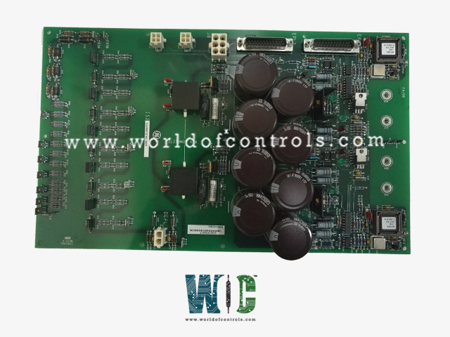
SPECIFICATIONS
Part No.: IS200EDEXG1BBB
Manufacturer: General Electric
Country of Manufacture: United States of America (USA)
Temperature Operating: -30 to 65 o C
Input filter: Hardware filter, 4 ms
Excitation voltage: Nominal 24 V dc,
Product Type: Exciter De-Excitation Control Board
Availability: In Stock
Series: EX2100e
Functional Description
IS200EDEXG1BBB is an Exciter De-Excitation Control Board developed by GE. It is a part of EX2100e excitation system. The Exciter De-Excitation control board serves as the central component within the de-excitation module, playing a critical role in safeguarding generator systems during emergency shutdowns. Utilizing redundant control measures, dual firing commands are transmitted via the EXTB, activating the firing circuitry.
Features
- When a shutdown event occurs and the field breaker or contactors open, the module swiftly removes stored energy from the generator field, preventing potential damage or hazards.
- EDEX accomplishes this through several key functions:
- SCR Firing: The board facilitates the firing of Silicon Controlled Rectifiers (SCRs), which are essential for controlled energy dissipation from the generator field.
- Conduction Sense Feedback: It provides feedback mechanisms to monitor the conduction status, ensuring the efficient operation of the de-excitation process.
- Voltage Retention: Ensures voltage retention even in the event of a power failure, allowing for continued functionality and safety measures during critical moments.
- The initiation of de-excitation is managed by the EMIO (Exciter Module Input/Output) board, which triggers the process on the EXTB (Exciter Transfer Board). The EXTB board, in turn, initiates the opening of the 41dc contactor (MDA/MDB) or breaker, and subsequently relays de-excitation signals from auxiliary contacts to the SCR firing circuits on the board.
- It's important to note that there are two distinct types of EDEX boards available:
- Group 1: Designed for SCR de-excitation, this board is optimized to coordinate the controlled dissipation of energy using Silicon Controlled Rectifiers.
- Group 2: Tailored for diode de-excitation, this board is specialized in managing the de-excitation process through diode-based circuits.
- This modular control scheme ensures the effective and safe operation of de-excitation processes across various generator systems, offering adaptability and reliability in critical scenarios.
Voltage Hold Up Circuit
- Voltage Retention: The Voltage Hold Up Circuit is responsible for retaining voltage on both the positive and negative 24 V dc lines within the module. This ensures that even if there is a total power failure, the necessary voltage levels are maintained, enabling the SCR to be fired promptly when required.
- Emergency Preparedness: By retaining voltage on these lines, the circuitry ensures that the module remains prepared to initiate the de-excitation process at any moment, even under adverse conditions such as power outages. This capability is critical for maintaining the safety and integrity of the generator system during emergency shutdowns.
- External De-Excitation Contacts: Additionally, the Voltage Hold Up Circuit also provides voltage for wetting the external de-excitation contacts. This ensures that the firing command necessary for de-excitation remains available even after a power failure. Wetting the contacts ensures a reliable electrical connection, guaranteeing that the de-excitation process can be executed seamlessly when required.
Application data
- Power Input: Power is supplied to the board through connectors J1 and J2. These connectors serve as entry points for the primary power source, ensuring that the board receives the necessary electrical supply to operate effectively.
- De-Excitation Signal Connection: A cable originating from the EXTB carrying the de-excitation signal is connected to connector J8 on the board. This connection allows for seamless communication between the EXTB and the board, facilitating the initiation of the de-excitation process as required.
- Stab Connectors (E1B through E12): These stab connectors play a crucial role in configuring the EDEX board to suit specific requirements. They facilitate the connection of wire jumpers, enabling the selection of break over diodes and current limiting resistors. By adjusting these configurations, users can tailor the voltage and size of the SCR (Silicon Controlled Rectifier) to match the demands of the application, ensuring optimal performance and compatibility.
- SCR Anode Connection: Stab connector E1A is wire jumpered to the SCR anode, establishing a crucial connection point within the firing circuitry. This connection ensures the proper functioning of the SCR, allowing it to be activated effectively in response to firing commands received from the EXTB.
The WOC team is always available to help you with your EX2100e requirements. For more information, please contact WOC.
Frequently Asked Questions
What is IS200EDEXG1BBB?
It is an Exciter De-Excitation Control Board developed by GE under the EX2100e series.
What is the cable connection used between Follower boards?
The cable utilized between Follower boards is equipped with a 25-pin D connector labeled EPL2.
How is the EPL2 connector configured?
The EPL2 connector is configured with 25 pins, facilitating the transmission of signals between interconnected Follower EDEX boards.
What is the purpose of the cable between Follower EDEX boards?
The cable serves to establish communication and signal transmission between interconnected follower boards, enabling coordinated operation and control within the de-excitation system.
Can the cable be used for connections other than between follower boards?
The cable labeled EPL2 with a 25-pin D connector is specifically designed for interconnecting Follower EDEX and may not be suitable for other applications or connections.
