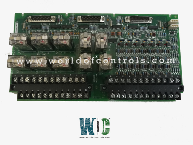
World Of Controls understands the criticality of your requirement and works towards reducing the lead time as much as possible.
IS200ECTBG1ACB - Exciter Contact Terminal Board is available in stock which ships the same day.
IS200ECTBG1ACB - Exciter Contact Terminal Board comes in UNUSED as well as REBUILT condition.
To avail our best deals for IS200ECTBG1ACB - Exciter Contact Terminal Board, contact us and we will get back to you within 24 hours.
SPECIFICATIONS:
Part Number: IS200ECTBG1ACB
Manufacturer: General Electric
Series: EX2100
Product Type: Exciter Contact Terminal Board
Function: Controls two trip relays
Relay Labels: K1M1, K2M1
Relay Type: Form-A, 2 parallel NC contacts
Relay Coil Voltage: 24 V DC
Max Relay Contact Current: 5 A
Max Relay Contact Voltage: 125 V DC
Dimensions: 11.00 x 9.00 x 3.00
Operating Temperature: -20°C to +60°C
Repair: 3-7 Days
Availability: In Stock
Country of Origin: United States
Manual: GEI-100457A
FUNCTIONAL DESCRIPTION:
IS200ECTBG1ACB is an Exciter Contact Terminal Board manufactured and designed by General Electric as part of the EX2100 Series used in GE Excitation Control Systems. The IS200ECTB terminal board supports excitation contact outputs and inputs in the EX2100 Excitation Control. There are two versions: the ECTBG1 board is only used in the redundant control, and the ECTBG2 board is only used in the simplex control. Each board contains two trip outputs driving a customer lockout, controlled by the EMIO board. There are also four general-purpose Form-C contact outputs controlled by the EMIO board. Six auxiliary contact inputs are powered (wetted) with 70 V dc and monitored by ECTB. Also, the 52G and 86 G contact inputs are powered with 70 V dc and monitored. In the redundant control, power comes from both the M1 and M2 controllers
TRIP RELAY OUTPUTS (SIMPLEX/REDUNDANT):
The ECTBG1 module, driven by the EMIO in M1, controls two trip relays typically used as customer lockout drivers, with the relays powered by 24 V DC from the M1 controller. Each lockout is actuated by a single relay using two parallel normally closed contacts, labeled on the board as K1M1 and K2M1, ensuring reliable operation. For redundant control, the module uses a 2-out-of-3 voting circuit, where three inputs drive three separate relays, and at least two of the three contacts must close to generate a trip, providing enhanced system reliability and protection against single-point failures.
GENERAL PURPOSE RELAY OUTPUTS (SIMPLEX/REDUNDANT):
The ECTBG1 module manages four general-purpose relay outputs, with the relay drivers powered by 24 V DC from the M1 controller. Each relay is a Form-C type, providing normally open (NO), normally closed (NC), and common (COM) terminals, to which customer power, typically 125 V DC, is connected. On the circuit board, the relays are identified as K1GP, K2GP, K3GP, and K4GP, allowing clear identification and wiring. For redundant operation with the ECTBG1 module, the three input signals are processed through a voting mechanism within the relay driver, which then energizes the single relay coil, ensuring that the output operates reliably only when the required majority of inputs agree, thereby enhancing system safety and fault tolerance.
CONTACT INPUTS:
Contact input uses are similar in the simplex and redundant cases; however, the inputs are fanned to the M1, M2, and C controllers for redundant control. In simplex control, only the M1 controller is connected. Six customer-supplied auxiliary contact inputs are powered and monitored by ECTB using 70 V dc from plugs J13M1 and J13M2, is resistor resistor-isolated and supplied to the contacts. The wetting voltage can vary from 63 to 84 V dc. The state of the contact is monitored. The resulting signal drives a red indicating LED, and fans out to M1, M2, and C. One contact from 52G is monitored using the 70 V dc excitation in the same way as the auxiliary inputs. The status is indicated with a red LED. One contact from 86G is wetted with a nominal 70 V dc as above. The state of the contact is monitored by controllers M1, M2, and C.
WOC maintains the largest stock of OEM replacement parts for GE Excitation Control Systems, offering both unused and factory-tested rebuilt boards backed by a warranty for reliable performance. In addition to supplying components, we provide expert repair services for faulty boards, restoring them to full functionality. Our team of specialists is available 24/7 to support your OEM requirements, assist with component selection, installation, and system integration, and ensure prompt, cost-effective solutions. For pricing, availability, or technical assistance, customers can contact our team directly via phone or email.
What is the nominal customer power rating connected to the relay outputs?
Customer wiring is usually 125 V DC, connected to the relay contact terminals. This power is used to operate external circuits or devices.
How does redundancy work in ECTB boards?
ECTBG1 uses a 2-out-of-3 voting system for trip signals, reducing false trips. ECTBG2 applies voting logic in the relay driver before energizing the coil.
What designations are used for relays on ECTB boards?
On ECTBG1, relays are marked as K1M1 and K2M1, while ECTBG2 relays are marked K1GP to K4GP. These designations help in easy identification during maintenance.
What are the typical contact ratings?
Relay contacts are generally rated up to 125 V DC and 5 A. This makes them suitable for standard turbine and exciter system requirements.