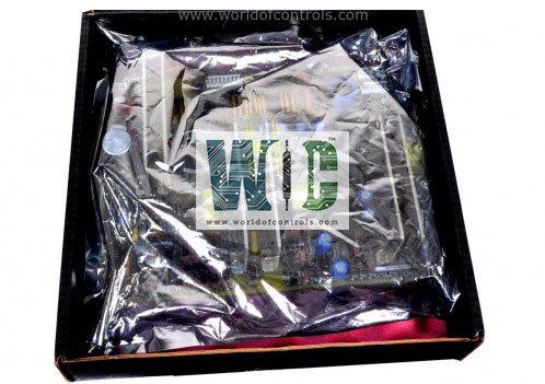
SPECIFICATIONS
Part Number: IS200EACFG3A
Manufacturer: General Electric
Series: EX2100
Function: Exciter Ac Feedback board
Availability: In Stock
Operating temperature: -30 to 65 degrees Celsius
Repair: 3-7 Day
Manual: GEI-100465
Country of Manufacture: United States (USA)
Functional Description
IS200EACFG3A is an Exciter Ac Feedback board developed by General Electric. It is a part of GE EX2100 system.�The Exciter AC Feedback Board (EACF) is designed to measure the exciter PPT AC supply voltage and current. This terminal board incorporates advanced functionalities for accurate and efficient signal processing. This board is essential in feedback and monitoring within exciter systems. Provides reliable feedback and control functionality in diverse operating conditions.
Features
- Three-Phase Voltage Measurement: The board contains built-in transformers for precise three-phase voltage measurement. These transformers enable accurate voltage sensing, ensuring optimal performance in monitoring and control systems.
- Flux/Air Core Coil Terminals: Equipped with terminals for two flux/air core coils, the board provides additional flexibility and compatibility for various signal inputs. High-frequency noise suppression is incorporated near the signal entry points, ensuring the integrity of flux/air core input signals.
- Output Connectivity: The voltage and current circuits fan out their outputs through three DB9 connectors. These connectors allow seamless interfacing with M1, M2, and C controllers, enabling effective communication and data transfer.
- Cable Compatibility: The board supports a cable length of up to 90 meters between the EACF and the EBKP backplane board, ensuring adaptability to different system layouts.
- Chassis Grounding for Signal Integrity: Cable shield terminal screws are located within three inches of the input screws, providing robust grounding to chassis and improving signal noise rejection.
- Installation and Placement: The EACF board is installed within the exciter auxiliary cabinet, ensuring secure housing and proximity to other exciter system components.
Board Layout
- Three-Phase Voltage Transformers (T1 to T4): The board features four transformers labeled T1, T2, T3, and T4, dedicated to measuring three-phase AC supply voltage. These transformers ensure accurate voltage transformation and signal conditioning for subsequent processing by the system.
- Voltage Input Terminals (TB1, TB2, TB3): Separate screw connectors labeled TB1, TB2, and TB3 are provided for connecting the voltage inputs of the three phases. This modular connection design facilitates easy installation and maintenance of the board in the exciter auxiliary cabinet.
- Flux/Air Core Coil Connections (TB4): Terminal block TB4 is specifically designated for wiring from two flux/air core coils. The wiring configuration allows for precise measurement and feedback from these input sources, enhancing the board's operational versatility.
- Sub-D Connectors (J504, J509, J514): The board is equipped with three 9-pin Sub-D connectors identified as J504,�J509,�J514. These connectors are designed for cable connections to the EBKP backplane, which serves as the interface to the EMIO boards. This setup ensures smooth communication and data transfer across different system components.
Replacement Procedures
- Open the auxiliary cabinet door where the EACF board is housed. Use a voltage tester to verify that all electrical circuits are de-energized before proceeding. This step is crucial to avoid electrical shock or damage to the equipment.
- Begin by carefully disconnecting all cables attached to the board. Confirm that all cables are correctly labeled with their respective connector names (as marked on the board). This labeling is essential to ensure an accurate and simplified reconnection process. Disconnect the wiring from the screw connectors labeled TB1, TB2, and TB3 for the three-phase voltage inputs. Disconnect the wiring from the TB4 terminal block, which is dedicated to the flux/air core coil inputs.
- Locate the three mounting screws securing the board to its standoffs. Use an appropriate screwdriver to remove these screws. Gently take out the EACF board, ensuring no damage occurs to adjacent components or wiring.
- Take the new EACF board and orient it in the exact position as the one removed. Align the board with the standoffs and secure it firmly using the three screws previously removed. Ensure the board is mounted securely to avoid operational issues.
- Reattach all cables and wires to their designated connectors on the new board, referring to the labels made during the disconnection step. The cables are connected to the correct terminals. Each cable and wire is securely seated at both ends to maintain reliable connectivity.
- Once the replacement process is complete, close the auxiliary cabinet door to ensure the system is enclosed and protected from external elements.
WOC has the largest stock of Speedtronic control spares. Please contact our staff by phone or email for pricing and availability on any parts and repairs
FREQUENTLY ASKED QUESTIONS
What is IS200EACFG3A?
It is an Exciter Ac Feedback board developed by General Electrics.
Where is the board located?
The board is installed within the exciter auxiliary cabinet, typically near other exciter system components.
What are the two versions of the EACF board, and how do they differ?
EACFG1 Designed for systems with input voltages up to 480 V RMS. EACFG2 Supports higher input voltages, up to 1000 V RMS. The choice between these versions depends on the specific voltage requirements of your application.
How long can the cable between the EACF board and the EBKP backplane be?
The cable connecting the board to the backplane can be up to 90 meters in length, offering flexibility in system layout.
