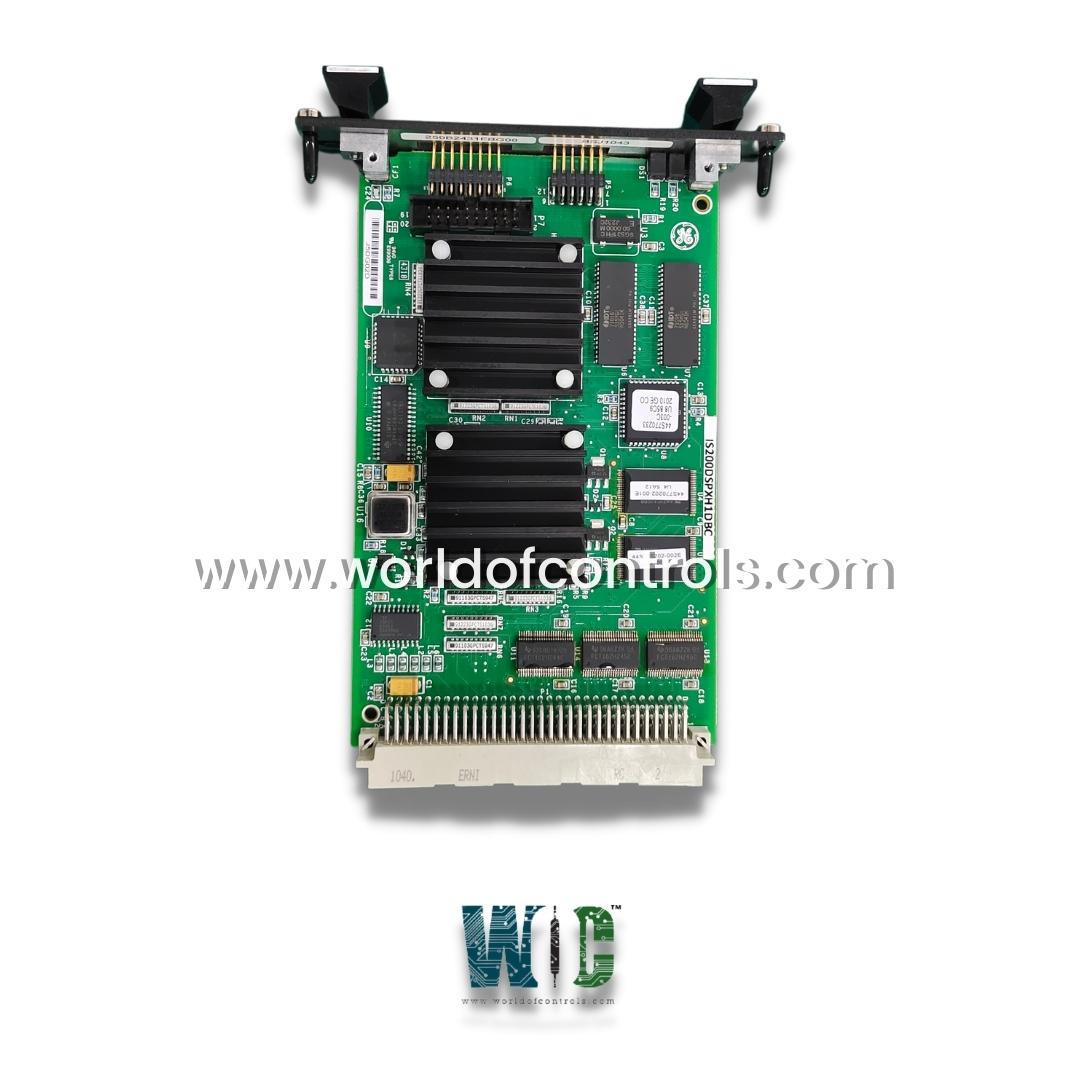
SPECIFICATIONS
Part No.: IS200DSPXH1DBC
Manufacturer: General Electric
Country of Manufacture: United States of America (USA)
Temperature Operating: -30 to 65oC
PCB Coating: Conformal Coating
Manual: GEI-100488
Product Type: Digital Signal Processor Control Board
Availability: In Stock
Series: EX2100
Functional Description
IS200DSPXH1DBC is a Digital Signal Processor Control Board developed by GE. It is a part of EX2100 control system. The Digital Signal Processor Control Board (DSPX) serves as the central control unit for various essential functions within Innovation Series drives and the EX2100 Excitation Control system. Its primary responsibilities include overseeing the regulation and gating functions for both the bridge and motor and managing generator field control functions for the Excitation Control.
Features
- The board is equipped with advanced logic, processing capabilities, and interface functions essential for seamless system operation. These functions are made possible through the integration of high-performance digital signal processors (DSPs), standard memory components, and an application-specific integrated circuit (ASIC) tailored to perform custom logic functions.
- Bridge and Motor Regulation: Orchestrates the regulation of the bridge and motor, ensuring precise control over their operation. This includes managing voltage and current levels to maintain optimal performance and stability.
- Gating Functions: Gating functions are also handled, enabling precise switching of power semiconductor devices to control the flow of electrical energy within the system.
- EX2100 Excitation Control: In addition to its role in drive systems, the board plays a crucial role in controlling generator field functions for the EX2100 Excitation Control system. This involves regulating the excitation of the generator field to maintain desired output characteristics.
- Hardware Components: The board is equipped with state-of-the-art hardware components, including a high-performance DSP, standard memory components for data storage and retrieval, and an ASIC designed to execute specialized logic functions tailored to the specific requirements of the control system.
Hardware Features
Digital Signal Processor (DSP)
- Processing Power: The DSP operates at a clock speed of 60 MHz, providing ample processing power to execute complex control algorithms and manage critical system functions effectively.
- Interrupt Handling: Four external interrupts are available during normal operation, enhancing the DSP's responsiveness and allowing it to promptly handle important events. These interrupts include stack overflow (INT0), inner loop load pulse (INT1), and two configurable inputs (INT2, INT3).
Memory Architecture
- FLASH Memory: Dedicated FLASH memory is allocated for storing DSP boot images, code execution, and configurable item storage. Additionally, system history records are stored in FLASH memory, ensuring essential data retention and system integrity.
- RAM: The DSPX board features RAM for dynamic data storage and code execution, providing temporary storage space for computational tasks and runtime data manipulation.
- NVRAM: Nonvolatile RAM (NVRAM) is utilized for persistent data storage, allowing critical system parameters and configuration settings to be retained even in the event of power loss or system restart.
- Add-Only Memory: Specialized add-only memory is allocated for board revision identification purposes, enabling easy identification of the board's hardware revision for maintenance and compatibility purposes.
Onboard Firmware
- Boot Loader: The boot loader is responsible for orchestrating the power-up sequence of the DSPX board. It initializes essential components and establishes the initial operating environment. It's crucial to note that the boot loader should not be reloaded in the field. It ensures the integrity and stability of the power-up process, safeguarding against potential errors or system failures.
- Application Code: The application code defines the specific control functions tailored for the drive or exciter product. It encompasses the algorithms and logic necessary for regulating and controlling various aspects of the system's operation. This code is loaded into the board through the Tool port on the exciter, providing a streamlined process for updating and implementing control functionalities.
- Configuration Parameters: Configuration parameters dictate the behavior and operation of the drive or exciter product. These parameters include settings related to performance, operation modes, and system configurations. Exciter parameters are loaded over the Unit Data Highway, facilitating efficient communication and parameter transfer. Drive parameters, on the other hand, are loaded through various interfaces such as a serial port, ISBus, or Ethernet to ACL_, depending on the system configuration.
The WOC team is always available to help you with your EX2100 requirements. For more information, please contact WOC.
Frequently Asked Questions
What is IS200DSPXH1DBC?
It is a high-speed serial-link interface board developed by GE under the EX2100 series.
What functions does the P1 connector on the board serve?
The P1 connector plays a pivotal role in facilitating communication and control within the system. It provides memory-mapped process bus address space with four chip select signals, supporting interfaces to bridge and customer input/output (I/O). Additionally, it offers individual controls for a standard UART serial interface to a programmer board and a configuration tool.
What is the purpose of the P5 emulator port on the board?
The P5 emulator port, situated on the board's front panel, serves as an interface to the TI emulator port. This port facilitates various functions, including emulation and FLASH programming. It provides a scan interface akin to JTAG, allowing for emulation activities and efficient programming of FLASH memory.
How does the P1 connector contribute to system functionality?
The P1 connector's versatile design enables seamless integration of external devices and expansion modules, enhancing system flexibility and scalability. By offering multiple interfaces such as UART serial, ISBus serial, and chip select signals, it facilitates efficient communication and control, catering to diverse application requirements.
Can the P5 emulator port be used for firmware development and debugging?
Yes, the P5 emulator port supports firmware development and debugging activities. Its interface to the TI emulator port allows for emulation functionalities, enabling developers to test and debug firmware code efficiently. Additionally, the port facilitates FLASH programming, streamlining the firmware update process.
