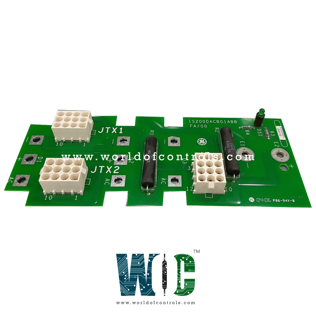
World Of Controls understands the criticality of your requirement and works towards reducing the lead time as much as possible.
IS200DACBG1ABC - AC/DC Converter Power Supply Module is available in stock which ships the same day.
IS200DACBG1ABC - AC/DC Converter Power Supply Module comes in UNUSED as well as REBUILT condition.
To avail our best deals for IS200DACBG1ABC - AC/DC Converter Power Supply Module, contact us and we will get back to you within 24 hours.
SPECIFICATIONS:
Part Number: IS200DACBG1ABC
Manufacturer: General Electric
Series: EX2100
Product Type: AC/DC Converter Power Supply Module
Number of channels: 6
Input Span: 1-5 V dc
Input Voltage (AC): 120–240 VAC
Outputs: 24 V outputs
Analog output current: 0-20 mA
Input Frequency: 47–63 Hz
Output Voltage (DC): 24 VDC, 48 VDC
Output Power Rating: Up to 200 W
Operating temperature: -30 to 65 °C
Size: 26.41 cm High x 21.33 cm
Repair: 3-7 days
Availability: In Stock
Country of Origin: United States
Manual: GEH-6633
FUNCTIONAL DESCRIPTION:
IS200DACBG1ABC is an AC/DC Converter Power Supply Module manufactured and designed by General Electric as part of the EX2100 Series used in GE Excitation Control Systems. Some EX2100 exciters may contain DACBG1ABC power supply modules. An AC/DC Converter Power Supply Module is an electronic device used to convert alternating current (AC) voltage from a mains power supply into direct current (DC) voltage suitable for powering electronic circuits or devices. These modules are commonly used in various applications where stable and reliable DC power is required. Both DACBG1ABC modules can supply power to M1, M2, or C controllers. The power source for the DACBG1ABC modules does not have a separate switch within the EX2100. Voltage must be measured at the terminal board to verify that the external power source to the DACB module is OFF.
INSTALLATION:
OPERATION:
The AC/DC Converter Power Supply Module, particularly the DACBG1ABC module used in the EX2100 Excitation Control System, operates by converting alternating current (AC) from an external mains source into a stable, regulated direct current (DC) output. The module accepts an AC input, typically in the range of 120–240 VAC at 50/60 Hz. This input first passes through EMI filters and surge protection circuits to eliminate electrical noise and shield the module from power surges. The filtered AC voltage is then rectified into high-voltage DC, which is further processed through high-frequency switching circuits. Using Pulse Width Modulation (PWM), the module regulates and converts the voltage to the desired output level, commonly 24V, 48V, or 125V DC, depending on the system requirements.
The DACBG1ABC module is also equipped with built-in protection features such as overvoltage, overcurrent, and thermal shutdown to safeguard the connected components and itself. These modules often include visual indicators like LEDs to show operational status or faults. It is important to note that the DACB module does not have a built-in power switch within the EX2100 system. Therefore, technicians must verify that the external power supply is disconnected by measuring voltage at the terminal board before performing any maintenance. This operational design ensures both continuous performance and safety in high-reliability applications like generator excitation systems.
WHY PURCHASE OR REPAIR THROUGH WOC?
WOC maintains one of the industry’s largest and most reliable inventories of replacement parts for GE Excitation Control Systems, supplying new, surplus, and fully refurbished components each rigorously tested and backed by a dependable warranty. Beyond parts delivery, we offer specialized repair and refurbishment services for faulty or aging boards, ensuring extended equipment life and reduced downtime. Our team of OEM and automation experts is available 24/7 to provide technical guidance, troubleshooting support, system upgrade assistance, and fast response for urgent requirements. Whether you’re looking for immediate replacements, long-term maintenance solutions, or professional engineering support, WOC is committed to keeping your excitation systems operating with maximum reliability and efficiency. For pricing, availability, or technical assistance, contact us anytime by phone or email.
What is the IS200DACBG1ABC module?
The IS200DACBG1ABC is an AC/DC Converter Power Supply Module from General Electric, part of the EX2100 Series used in GE Excitation Control Systems. It converts incoming AC voltage into stable DC power to operate controllers and other system components. This module is essential for maintaining reliable and continuous exciter system operation.
What is the input voltage range for this module?
The DACBG1ABC accepts an AC input voltage ranging from 120 to 240 VAC at 47–63 Hz. This flexible input range allows it to operate in various power supply environments. It also includes surge protection and EMI filtering to ensure stable operation.
What DC outputs does the module provide?
It provides regulated DC outputs of 24 VDC and 48 VDC, suitable for powering controllers and excitation circuits. The outputs are designed to remain stable even under fluctuating load conditions. This ensures the reliable performance of connected devices.