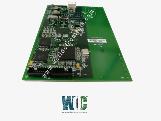
World Of Controls understands the criticality of your requirement and works towards reducing the lead time as much as possible.
IS200ADIIH1AAA - Auxiliary Drive to ISBus Interface Board is available in stock which ships the same day.
IS200ADIIH1AAA - Auxiliary Drive to ISBus Interface Board comes in UNUSED as well as REBUILT condition.
To avail our best deals for IS200ADIIH1AAA - Auxiliary Drive to ISBus Interface Board, contact us and we will get back to you within 24 hours.
SPECIFICATIONS:
Part Number: IS200ADIIH1AAA
Manufacturer: General Electric
Series: Innovation
Number of Channels: 8
Maximum lead resistance: 15 Ohm
Product Type: Auxiliary Drive to ISBus Interface Board
Microprocessor: Intel Pentium 133 MHz
ISBus interface: Twisted pair RJ-45
Power requirements: +5 V dc
Size: 33.0 cm wide x 17.08 cm
Technology: Surface Mount
Operating temperature: 0 to 60°C
Temperature: 30 to 65°C
No.of Analog Voltage Inputs: 6
Repair: 3-7 Day
Availability: In Stock
Country of Origin: United States
Manual: GEI-100305
FUNCTIONAL DESCRIPTION:
IS200ADIIH1AAA is an Auxiliary Drive to ISBus Interface Board manufactured and designed by General Electric as part of the Innovation Series used in GE Innovation Control Systems. The IS200ADII Auxiliary ISBus (Innovation Series Bus) Interface board (ADII) interfaces an AcDc2000 drive to an ISBus Local Area Network (LAN). The ADII board resides on the backside of the first board carrier of the AcDc2000 drive. The ADII board connects to the DS200LDCC Drive Control/LAN Communications board (LDCC) through the LNPL ribbon cable and COM1 wire. The ADII board receives power through the 2PL power cable from the AcDc2000 drive's power supply board. The ADII board includes a bypass relay to maintain ISBus electrical continuity if the drive is powered down (no external bypass module is required).
The interface signal map is derived from the Innovation Series drive system applications signal map. Many references and feedbacks are generic and Ac/Dc2000 drive blockware must be created to imitate the Innovation Series drive functionality. The ADII board provides an integer variable map between the drive and controller. The integers must be scaled to the AcDc2000 units (given in the signal map definition). Configuration of the interface is done with either the local keypad on the LDCC board (see Figure 1) or the GE Control System Toolbox (toolbox). Refer to the section, Data Mapping. The ADII board has no fuses or hardware jumpers. Refer to the section, Application Data for information on the LED indicators, test points, and connectors that are on the board.
ISBus:
The ISBus has one controller (drop 0) and no more than 31 nodes (1-31). The master sends out a stream of bytes containing each ISBus node's references. As the nodes receive the stream of bytes, they pass the stream on to the next node substituting their feedback data in place of their reference data in the stream. When the stream of bytes returns to the master, it contains each node's feedback data. The ISBus frame rate is programmable and can be 1, 2, 4, or 8 milliseconds (ms). The ADII board requires a time delay of 200 µsec. This allows the LAN Control Processor (LCP on the LDCC board) to write the driveís feedback into the ISBus controller before the start of the next frame.
CONNECTIONS AND PERFORMANCE:
The ADII board interfaces to the ISBus through two RJ45 connectors, P2 (TX/OUT) and P3 (RX/IN). The user cables are run into the drive package and directly to the ADII board. The TX/OUT connector (P2) ties to the RX/IN connector (P3) of the next device on the ISBus. The RX/IN connector (P3) ties to the TX/OUT connector (P2) of the previous device on the ISBus. On the ISBus, the controller sends control bits and references for each drive in a single stream of bytes. The first drive wired to the controller receives the stream of bytes, retrieves its command bits and references, and passes the stream of bytes onto the next drive substituting its feedback bits and variables for the command bits and references. When the controller receives the stream of bytes from the bus, it receives the feedback bits and feedback variables from the drives.
DATA MAPPING:
The drive is configured through its keypad or by the toolbox. Once configured, the drive exchanges a fixed set of integer variables with the controller during each ISBus scan.
The integer variable interface map consists of 17 words of reference and 17 words of feedback. The first two words of reference and feedback contain 32 bits. The remaining 15 words of reference and feedback contain signed integer variables. Tables 3 and 4 define the system application signal map and Boolean signals. Table 5 contains AcDc2000 reference and feedback values.
WOC has the largest stock of OEM Replacement Parts for GE Innovation Turbine Control systems. We can also repair your faulty boards and supply unused and rebuilt boards backed up with a warranty. Our team of experts is available round the clock to support your OEM needs. Our team of experts at WOC is happy to assist you with any of your automation requirements. For pricing and availability on any parts and repairs, kindly contact our team by phone or email.
What is an Auxiliary Drive to ISBus Interface Board?
The Auxiliary Drive to ISBus Interface Board is a specialized device that acts as a communication interface between auxiliary drives and the ISBus (Industrial Standard Bus) network. It enables the seamless transfer of data, ensuring that auxiliary drives can integrate effectively into centralized control and monitoring systems commonly used in industrial and energy management applications.
What input and output options are available?
The board supports standard inputs from auxiliary drives, including both analog and digital signal formats. On the output side, it converts these signals into ISBus-compatible formats, enabling seamless integration with centralized control networks. This capability ensures efficient communication and real-time data exchange between devices.
What are the power requirements of the board?
The board operates on a 24V DC power supply with a tolerance of ±10%. Its power consumption is typically less than 10W, making it an energy-efficient solution for industrial applications. This low power requirement also ensures reliable operation in setups with limited power capacity.