World Of Controls understands the criticality of your requirement and works towards reducing the lead time as much as possible.
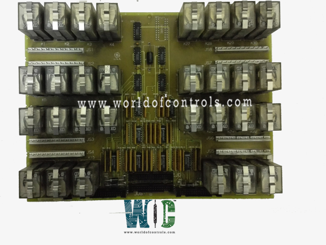
DS200TCRAG1B - Relay Output Board is available in stock which ships the same day.
DS200TCRAG1B - Relay Output Board comes in UNUSED as well as REBUILT condition.
To avail our best deals for DS200TCRAG1B - Relay Output Board, contact us and we will get back to you within 24 hours.
SPECIFICATIONS:
Part Number: DS200TCRAG1B
Manufacturer: General Electric
Series: Mark V LM
Number of Channels: 8
Product Type: Relay Output Board
Sample Rate: Up to 100 kS/s per channel
Power Requirements: +5 V dc, 6 A
Logic Levels: 3.3V and 5V compatible
Operating Temperature: 0�C to 70�C
Storage Temperature: -40�C to 85�C
Size: 30.48cm High x 21.33cm
Mounting: 4 mounting Holes
Repair: 3-7 Day
Availability: In Stock
Country of Origin: United States
Manual: GEH-6353B
FUNCTIONAL DESCRIPTION:
DS200TCRAG1B is a Relay Output Board manufactured and designed by General Electric as part of the Mark V LM Series used in the Line of Microprocessor aero-derivative turbine Control Systems. The Relay Output Board (TCRA), located in the
TCRA CONNECTORS:
TCA CONTACT OUTPUT CIRCUITS:
The relays on the TCRA boards are operated by signals from the control sequencing program and sent to the STCA board over the COREBUS to the I/O Engine in the
WOC has the largest stock of OEM Replacement Parts for the GE Line of Microprocessor Aero-derivative turbine Control Systems. We can also repair your faulty boards and supply unused and rebuilt boards backed up with a warranty. Our team of experts is available round the clock to support your OEM needs. Our team of experts at WOC is happy to assist you with any of your automation requirements. For pricing and availability on parts and repairs, kindly contact our team by phone or email.
How many channels does the board support?
The board is equipped with eight channels, which allow efficient and precise relay output control. Each channel ensures the proper transmission of electrical signals required for the functioning of turbine components. The availability of multiple channels enhances the board�s ability to handle complex control processes within the system.
What is the sample rate of this board?
The Relay Output Board operates with a sample rate of up to 100 kS/s per channel. This high-speed sampling capability ensures that the board can process and transmit signals quickly and accurately, which is crucial for real-time turbine system operations and control.
What are the power requirements for this board?
The board operates on a +5V DC power supply with a current requirement of 6A. These power specifications ensure optimal functionality and compatibility with other components in the turbine control system, allowing for stable and efficient relay operations.
What logic levels does the board support?
This board supports both 3.3V and 5V logic levels, making it versatile and compatible with various control system architectures. The flexibility in logic-level support ensures that it can be integrated seamlessly into different configurations within the Mark V LM series.