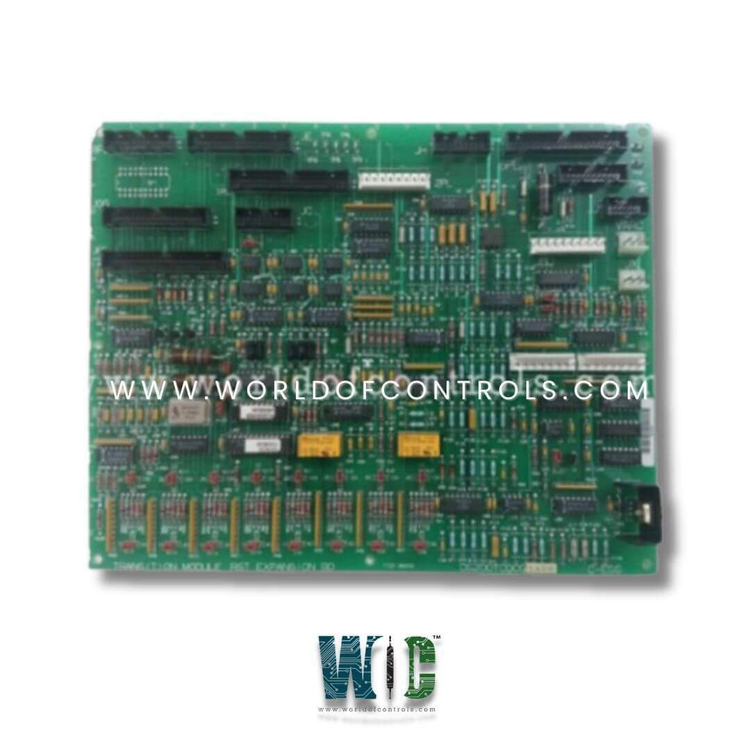
DS200TCQCG1AGD - Analog I/O Expander Board

DS200TCQCG1AGD - Analog I/O Expander Board DS200TCQCG1AGD - Analog I/O Expander Board

World Of Controls understands the criticality of your requirement and works towards reducing the lead time as much as possible.

DS200TCQCG1AGD - Analog I/O Expander Board is available in stock which ships the same day.

DS200TCQCG1AGD - Analog I/O Expander Board comes in UNUSED as well as REBUILT condition.

To avail our best deals for DS200TCQCG1AGD - Analog I/O Expander Board, contact us and we will get back to you within 24 hours.

SPECIFICATIONS

Part No.: DS200TCQCG1AGD
Manufacturer: General Electric
Product Type: Analog I/O Expander Board
Product Description: Analog I/O Expander Board
Country of Manufacture: United States (USA)
Series: Mark V

Functional Description

DS200TCQCG1AGD is an Analog I/O Expander Board developed by GE. It is a part of Mark V Series. It condition and scales signals from sources, including shaft speed, fuel flow, and power measurements, ensuring that data is efficiently transmitted to the relevant boards in the system. With its array of connectors and jumper settings, the TCQC board supports many configurations to meet the specific needs of turbine monitoring and control.

Servo Valve Regulator Output Circuits

  • The board processes the current from the TCQA board, scaling it using jumpers to control the positioning of the servo valves. The hardware jumpers on the TCQC board are responsible for configuring both the reference feedback and the output current range. Additionally, the TCQC board houses the servo clamp relay and the suicide relays.
  • When the suicide relays are energized, the signal is grounded by bypassing the servo valves, which causes the servo valve to drift to its bias position. Energizing the servo clamp relays applies a positive current to the servo valve.
  • The signal from the CSP is written to the TCQA board and then transmitted to the TCQC board, activating the suicide relays. In emergency situations, a direct signal written to the TCQC board via the TCEA board will activate the servo clamp relays.

Pulse Rate Input Circuit

  • The high-pressure shaft pulse rate signals are received from the TCQE board through the JJ connector. These signals originate from the PTBA board in the P1 core. The high-pressure shaft signals are passed to the TCQA board via the JE connector, where they are scaled and conditioned before being transmitted to the STCA board via the 3PL connector.
  • Pulse rate inputs from magnetic speed sensors and TTL-type sensors, located on the TBQB terminal board, pass through the TCQC board via the JH connector. Additional magnetic pickup pulse rate signals can be accessed on the QTBA board and are read via the JGG connector.
  • It is important to note that some signals on the PTBA terminal board may also be routed to the QTBA terminal board, but these should not be used on both boards simultaneously. The corresponding screws on the QTBA terminal board will not be available if signals are also connected to the PTBA terminal board.

The most extensive assortment of GE Speedtronic Mark V control replacement components is available at World of Controls. Our experts are available to assist you with your Mark V requirements at any time. Please contact WOC if you require any additional information.

Frequently Asked Questions

What is DS200TCQCG1AGD?
It is an Analog I/O Expander Board developed by GE.

Can the board handle multiple analog signals?
Yes, the board is capable of handling and conditioning multiple analog signals. It scales and processes signals from sensors, such as megawatt transducers and shaft speed sensors, and sends them to the appropriate boards for further analysis.

What is the function of the IONET termination on the TCQC board?
The IONET termination on the TCQC board is used to terminate communication signals between the TCEA board in the P1 core and the R1 core. This allows for proper signal transmission within the control system.