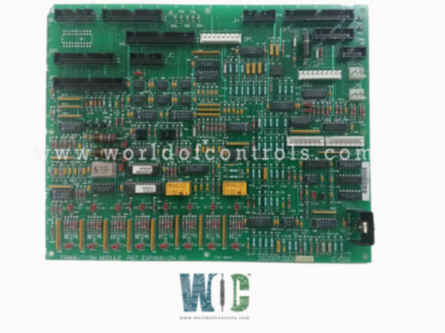
World Of Controls understands the criticality of your requirement and works towards reducing the lead time as much as possible.
DS200TCQCG1AEB - Analog I/O Expander Board is available in stock which ships the same day.
DS200TCQCG1AEB - Analog I/O Expander Board comes in UNUSED as well as REBUILT condition.
To avail our best deals for DS200TCQCG1AEB - Analog I/O Expander Board, contact us and we will get back to you within 24 hours.
Part No.: DS200TCQCG1AEB
Manufacturer: General Electric
Product Type: Analog I/O Expander Board
Product Description: Analog I/O Expander Board
Country of Manufacture: United States (USA)
Series: Mark V
DS200TCQCG1AEB is an Analog I/O Expander Board developed by GE. It is a part of Mark V Series. It is designed to scale and condition analog signals, enhancing the overall system's ability to process inputs from terminal boards across the I/O cores. This expansion board provides additional signal processing capabilities, supporting functions like shaft speed monitoring, fuel flow signals, and power signal conditioning.
The most extensive assortment of GE Speedtronic Mark V control replacement components is available at World of Controls. Our experts are available to assist you with your Mark V requirements at any time. Please contact WOC if you require any additional information.
What is DS200TCQCG1AEB?
It is an Analog I/O Expander Board developed by GE.
What types of signals does the board handle?
The board processes signals from megawatt transducers, high-pressure shaft speed, liquid fuel flow, and other analog signals. It also handles pulse rate signals from sensors like the high-pressure shaft and transfers them to other boards in the system.
How does the board communicate with other modules?
The board communicates with other modules like the STCA board and TCQA board via I/O connectors such as the 19PL and JE. It ensures the proper scaling and conditioning of signals, which are then processed by other components for turbine control.
How do I configure the board?
The board is configured using hardware jumpers. Jumpers 1-16 adjust the output current range for servo outputs, and jumpers 25-36 provide additional feedback scaling options. There are also jumpers for enabling features like RS232 port testing, the stall timer, and factory test oscillators.
What is the purpose of the 19PL connector?
The 19PL connector carries a wide variety of signals, including megawatt, generator, bus, compressor stall detection, and high-pressure shaft pulse rate signals. It also carries power bus and neutral bus signals, facilitating communication between the TCQC board and other components such as the STCA board.