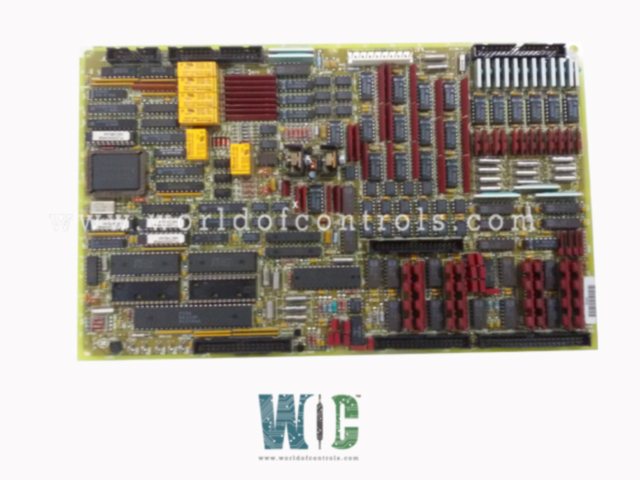
World Of Controls understands the criticality of your requirement and works towards reducing the lead time as much as possible.
DS200TCQAG1AEC - Analog I/O Board is available in stock which ships the same day.
DS200TCQAG1AEC - Analog I/O Board comes in UNUSED as well as REBUILT condition.
To avail our best deals for DS200TCQAG1AEC - Analog I/O Board, contact us and we will get back to you within 24 hours.
SPECIFICATIONS:
Part Number: DS200TCQAG1AEC
Manufacturer: General Electric
Series: Mark V LM
Product Type: Analog I/O Board
Power Requirements: +5 V dc, 6 A
Number of relay channels: 12
Power supply voltage: 28 V dc
Mounting: DIN-rail mounting
Technology: Surface mount
Operating temperature: -30 to +65°C
Size: 15.9 cm high x 17.8 cm
Repair: 3-7 Day
Availability: In Stock
Country of Origin: United States
Manual: GEH-6153
FUNCTIONAL DESCRIPTION:
DS200TCQAG1AEC is an Analog I/O Board manufactured and designed by General Electric as part of the Mark V LM Series used in GE Speedtronic Control Systems. The Analog IO Board (TCQA) scales and conditions many of the analog signals read in by terminal boards mounted on the I/O cores
TCQA CONNECTORS:
TCQA CONFIGURATION:
Hardware: Hardware jumpers J1 and J2 are used to select the mA output circuits. J5 and J6 are used to configure the mA outputs current range, either 20 mA maximum or 200 mA maximum. J7 is used for the RS232 port for card tests. J8 enables an oscillator.
Software: I/O Configuration constants for the thermocouples, pulse rates, vibrations, LVDT positions, and the 4-20 mA inputs and outputs are entered in the I/O Configuration.
WOC has the largest stock of GE Speedtronic Control System Replacement Parts. We can also repair your faulty boards. WORLD OF CONTROLS can also supply unused and rebuilt backed-up with a warranty. Our team of experts is available round the clock to support your OEM needs. Our team of experts at WOC is happy to assist you with any of your automation requirements. For pricing and availability on any parts and repairs, kindly get in touch with our team by phone or email.
What is an Analog I/O Board?
An Analog I/O board is a hardware component that facilitates the exchange of analog signals between a computer or controller and external devices. It is commonly used in applications where real-world signals, which vary continuously, need to be processed or controlled.
What are the key functions of an Analog I/O Board?
The primary functions of an Analog I/O board include receiving analog signals from external sensors (input channels) and sending analog signals to actuators or control systems (output channels). It serves as a bridge between the digital world of computers/controllers and the analog world of real-world signals.
How does an Analog I/O Board differ from a Digital I/O Board?
Analog I/O boards deal with continuous signals, while Digital I/O boards handle discrete signals (on/off or high/low). Analog I/O boards are used for applications where signal levels vary smoothly over a range, whereas digital boards are suitable for tasks involving binary states.