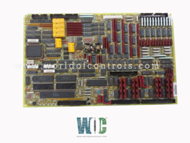
World Of Controls understands the criticality of your requirement and works towards reducing the lead time as much as possible.
DS200TCQAG1ADB - RST Analog Input/Output Board is available in stock which ships the same day.
DS200TCQAG1ADB - RST Analog Input/Output Board comes in UNUSED as well as REBUILT condition.
To avail our best deals for DS200TCQAG1ADB - RST Analog Input/Output Board, contact us and we will get back to you within 24 hours.
SPECIFICATIONS:
Part Number: DS200TCQAG1ADB
Manufacturer: General Electric
Series: Mark V LM
Number of Channels: 8
Product Type: RST Analog Input/Output Board
Input Range: ±10V
Resolution: 16-bit
Sample Rate: Up to 100 kS/s per channel
Input Impedance: >1 M Ohms
Overvoltage Protection: ±35V
Power Requirements: +5 V dc, 6 A
Logic Levels: 3.3V and 5V compatible
Operating Temperature: 0°C to 70°C
Storage Temperature: -40°C to 85°C
Size: 30.48cm High x 21.33cm
Mounting: 4 mounting Holes
Repair: 3-7 days
Availability: In Stock
Country of Origin: United States
Manual: GEH-6353B
FUNCTIONAL DESCRIPTION:
DS200TCQAG1ADB is an RST Analog Input/Output Board manufactured and designed by General Electric as part of the Mark V LM Series used in GE Linear Microprocessor Control Systems. The Analog I/O Board (TCQA) is responsible for scaling and conditioning a variety of analog signals received from terminal boards mounted on I/O cores
TCQA CONNECTORS:
TCQA CONFIGURATION:
Hardware Configuration: Hardware jumpers are used to set specific functionalities on the board. Jumpers J1 and J2 select the desired milliamp output circuits. Jumpers J5 and J6 define the output current range, allowing configuration for either a 20 mA or 200 mA maximum. Jumper J7 is designated for enabling the RS232 port used during card testing. Jumper J8 activates the onboard oscillator.
Software Configuration: Input and output parameters such as thermocouple types, pulse rates, vibration inputs, LVDT/LVDR positions, and 4–20 mA signal settings are configured using I/O Configuration constants. These are entered via the I/O Configurator tool on the operator interface.
TCQA PULSE RATE INPUT CIRCUIT:
The TCQA board includes circuitry for scaling and conditioning pulse rate inputs received from the TCQC board through the JE connector. These inputs originate from TTL (transistor-to-transistor logic) and magnetic pickup signals, which are routed through the QTBA and/or PTBA terminal boards. In core
TCQA 4-20 mA INPUT CIRCUITS:
The TCQA board provides the circuitry for the 4-20 mA and 0-1 mA input signals. The signals are read from the TBQC terminal board via the JB connector. The trans- ducer current is dropped across a burden resistor, and the voltage drop is read by the TCQA board and written to the I/O Engine via the 3PL connector. Hardware jumpers on the TBQC terminal board are used to select the current range of the input signals.
WOC has the largest stock of OEM Replacement Parts for GE Linear Microprocessor Control Systems. We can also repair your faulty boards and supply unused and rebuilt boards backed up with a warranty. Our team of experts is available around the clock to support your OEM needs. Our team of experts at WOC is happy to assist you with any of your automation requirements. For pricing and availability on parts and repairs, kindly contact our team by phone or email.
How are pulse rate signals handled by the TCQA board?
Pulse rate signals, such as those used for shaft speed measurements, are conditioned on the TCQA board after being received from the TCQC board via the JE connector. These signals originate from TTL (Transistor-Transistor Logic) and magnetic pickup sources connected through QTBA or PTBA terminal boards.
How are the 4–20 mA signals configured and utilized?
The 4–20 mA signals managed by the TCQA board are widely used in industrial systems for reliable analog communication of process values such as fuel pressure, flow rate, or stall detection. These signals are input and output through the JB connector and are first scaled and conditioned on the TCQA board to ensure compatibility with the control logic.
How are vibration signals managed by the TCQA board?
Vibration signals are brought in through the JG connector, which interfaces with the TBQB terminal board via the JGR connector. These signals are typically ±10 V analog signals from accelerometers or velocity sensors installed on the turbine.