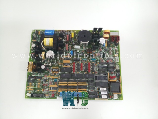
DS200TCEAG2BNE - TC2000 Emergency Overspeed Card

DS200TCEAG2BNE - TC2000 Emergency Overspeed Card DS200TCEAG2BNE - TC2000 Emergency Overspeed Card

World Of Controls understands the criticality of your requirement and works towards reducing the lead time as much as possible.

DS200TCEAG2BNE - TC2000 Emergency Overspeed Card is available in stock which ships the same day.

DS200TCEAG2BNE - TC2000 Emergency Overspeed Card comes in UNUSED as well as REBUILT condition.

To avail our best deals for DS200TCEAG2BNE - TC2000 Emergency Overspeed Card, contact us and we will get back to you within 24 hours.

SPECIFICATIONS:

Part Number: DS200TCEAG2BNE
Manufacturer: General Electric
Series: Mark V LM
Board rating: 125 V DC
Product Type: Emergency Overspeed Card
Impedance to the ground: 75 Ohms
Overspeed Trip: J28/J29
Connectors: J7, JK, JL, JW, JX1
Redundancy: Dual
Power Requirements: +5 V dc, 6 A
Operating temperature: -30 to +65°C
Size: 30.48cm High x 21.33cm
Mounting: 4 mounting Holes
Repair: 3-7 days
Availability: In Stock
Country of Origin: United States

FUNCTIONAL DESCRIPTION:

DS200TCEAG2BNE is a TC2000 Emergency Overspeed Card manufactured and designed by General Electric as part of the Mark V LM Series used in GE Speedtronic Control Systems. The Emergency Overspeed Board (TCEA), located in the Protective Core , functions as the high-speed protection circuitry and is commonly known as the Protective Processor. Within , three TCEA boards—designated as , , and —manage inputs for high and low shaft speed, flame detection, and automatic synchronization. These inputs are scaled and conditioned before being transmitted via the IONET to the STCA board in the core. Data transfer occurs through the JX1 connector on the TCEA board at location , which also receives input from boards and via JX1 and JX2 links.

The I/O Engine in processes the combined data from all three boards, applies a median select algorithm, and relays the results to the Control Engine via the COREBUS. Each TCEA board also sends emergency trip signals to the Turbine Trip Board (TCTG), triggering separate relays. The TCTG board employs a 2-out-of-3 voting logic based on the relay drivers to decide whether a turbine trip is required. Every TCEA board is powered independently and includes integrated power supply diagnostics.

TCEA CONNECTORS:

  • JK – Transmits input signals from the Protection Termination Expander Board (TCEB) in location two of the core to the corresponding TCEA boards. The TCEB collects and distributes all incoming signals through the JK connectors: JKX to , JKY to , and JKZ to .
  • JL – Carries emergency trip signals from each TCEA board to the Turbine Trip Board (TCTG) located in slot four of the core. Each TCEA board connects to a dedicated JL port on the TCTG: JLX for , JLY for , and JLZ for .
  • JW – Supplies 335 V DC power from the TCEA boards to the TCEB board for flame detectors. Power connections are routed through JW cables to the corresponding inputs on the TCEB: JWX for , JWY for , and JWZ for .
  • JX1 – Functions as a primary IONET connector in a daisy-chain configuration. JX1 on links directly to the TCQC board in the core, facilitating I/O signal communication between cores. JX1 on connects to JX2 on , and JX1 on connects to JX2 on .
  • JX2 – Completes the IONET daisy chain by linking between TCEA boards and extending the network. JX2 on connects to JX1 on , JX2 on on , and JX2 on continues the chain to the TCDA board in the core, ensuring seamless signal transmission to the I/O Engine in .

TCEA AUTOMATIC SYNCHRONIZING CIRCUIT:

The bus and generator voltages are initially received at the PTBA terminal board and routed to the TCEB board via the JV connector. From there, they are passed to the TCEA board through the JMP connector. The TCEA’s embedded software, stored in its EPROMs, manages both speed and voltage matching. Once it confirms that the generator and line voltages and frequencies are within the thresholds defined by the I/O Configuration constants, it sends a permissive signal to allow breaker closure. In parallel, the STCA board conducts a separate synchronization check and transmits a logic signal to the TCEA board. Both the permissive and synchronization signals must be valid for the breaker to close.

WOC has the largest stock of OEM Replacement Parts for GE Speedtronic Control Systems. We can also repair your faulty boards and supply unused and rebuilt boards backed up with a warranty. Our team of experts is available around the clock to support your OEM needs. Our team of experts at WOC is happy to assist you with any of your automation requirements. For pricing and availability on parts and repairs, kindly contact our team by phone or email.

FREQUENTLY ASKED QUESTIONS:

How do the TCEA boards communicate with each other and the rest of the system?

The TCEA boards communicate via daisy-chained IONET connections using JX1 and JX2 connectors. Board connects to via JX1 and JX2, connects to , and links to the TCQC board in the core, forming a continuous communication loop.

How are input signals routed to the TCEA boards?

Input signals such as speed, flame, and voltage values are first received by the Protection Termination Expander Board (TCEB) in location two of the core. These signals enter through the JK connector—JKX, JKY, or JKZ—corresponding to TCEA boards , , or . The signals are then forwarded to the respective TCEA boards for processing.

What is the function of the trip signal connections (JL)?

Each TCEA board connects to the Turbine Trip Board (TCTG) in the core through a dedicated JL connector—JLX, JLY, or JLZ. These JL lines carry emergency trip signals, and the TCTG board uses a 2-out-of-3 voting logic at the relay driver level to determine whether the turbine should trip. This design ensures redundancy and reliability in critical trip conditions.