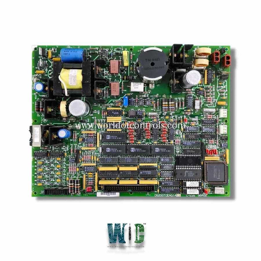
World Of Controls understands the criticality of your requirement and works towards reducing the lead time as much as possible.
DS200TCEAG1AEB - Emergency Overspeed Board is available in stock which ships the same day.
DS200TCEAG1AEB - Emergency Overspeed Board comes in UNUSED as well as REBUILT condition.
To avail our best deals for DS200TCEAG1AEB - Emergency Overspeed Board, contact us and we will get back to you within 24 hours.
Part No.: DS200TCEAG1AEB
Manufacturer: General Electric
Product Type: Emergency Overspeed Board
Product Description: Emergency Overspeed Board
Country of Manufacture: United States (USA)
Series: Mark V
DS200TCEAG1AEB is an Emergency Overspeed Board developed by GE. It is a part of Mark V Series. It serves as a high-speed protection, ensuring the turbine operates safely and within designated limits. Often referred to as the Protective Processor, the TCEA board is integral to monitoring turbine speed and initiating protective shutdowns when necessary.
The Emergency Overspeed Board is located in the Protective Core (P1) of the turbine control system. Within this core, three TCEA boards are utilized, each designated as the X, Y, and Z processors. These boards handle critical inputs related to:
These input signals are carefully scaled, conditioned, and then transmitted over the IONET network to the STCA board in the R1 core. The JX1 connector located on the TCEA board at location one (X) serves as the primary connection point to relay this data.
The TCEA boards in locations two (Y) and three (Z) continue to pass on their processed information through the JX1 and JX2 connectors via the X board. The I/O Engine in the R1 core takes the data from all three TCEA boards, performs a median select operation on the three values, and subsequently transfers the result across the COREBUS to the Control Engine. This ensures accurate decision-making for protection mechanisms and smooth operation.
One of the most important functions of the TCEA boards is their ability to send emergency trip signals to the Turbine Trip Board (TCTG). Each TCEA board sends a trip signal to separate relays on the TCTG board. The TCTG board uses a 2/3 voting mechanism based on relay drivers to determine whether an emergency shutdown of the turbine is necessary.
Each TCEA board is equipped with its own power supply and power supply diagnostics, ensuring independent operation and monitoring. This design helps maintain reliability and fault isolation within the control system.
The board features several key connectors that facilitate communication and power distribution:
The most extensive assortment of GE Speedtronic Mark V control replacement components is available at World of Controls. Our experts are available to assist you with your Mark V requirements at any time. Please contact WOC if you require any additional information.
What is DS200TCEAG1AEB?
It is an Emergency Overspeed Board developed by GE.
Where is the Overspeed Board located within the control system?
The TCEA board is located in the Protective Core (P1) of the turbine control system. Three boards are used in the core and are referred to as the X, Y, and Z processors.
How does the board protect the turbine?
The board sends emergency trip signals to the Turbine Trip Board (TCTG). Using a 2/3 voting mechanism, the TCTG board determines whether to shut down the turbine to prevent damage or accidents.
What connectors are used by the Overspeed Board?
The board utilizes several connectors for signal processing and power distribution. J7 for power distribution. JK, JL, and JW for input/output signals to/from the TCEB board and TCTG board. JX1 & JX2 for daisy-chained IONET communication between the TCEA boards and other components like the TCQC board.