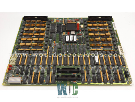
DS200TCDAG2BCB - Digital I/O Board

DS200TCDAG2BCB - Digital I/O Board DS200TCDAG2BCB - Digital I/O Board

World Of Controls understands the criticality of your requirement and works towards reducing the lead time as much as possible.

DS200TCDAG2BCB - Digital I/O Board is available in stock which ships the same day.

DS200TCDAG2BCB - Digital I/O Board comes in UNUSED as well as REBUILT condition.

To avail our best deals for DS200TCDAG2BCB - Digital I/O Board, contact us and we will get back to you within 24 hours.

SPECIFICATIONS

Part No.: DS200TCDAG2BCB
Manufacturer: General Electric
Country of Manufacture: United States of America (USA)
Product Type: Digital I/O Board
Availability: In Stock
Series: Mark V

Functional Description

DS200TCDAG2BCB is a Digital I/O Board developed by GE. It is a part of the Mark V control system. Located within the digital I/O cores such as Q11, Q51, and Q21 if present. It plays a crucial role in processing digital contact input signals from DTBA and DTBB terminal boards, as well as contact output signals (relay/solenoid) from TCRA boards. These processed signals are then transmitted over the IONET to the board located in R1 and R2 (if Q21 is installed) and the CTBA terminal board in R5. This allows for seamless communication and signal processing across various components within the system.

Connectors and Their Functions

  • JP - Power Distribution: Distributes power from the TCPS board in the R1, R2, and R5 cores to the Q11, Q21, and Q51 cores, respectively. This ensures proper power flow to the necessary components in each core.
  • JQ - Contact Input Signal Connection (DTBA): Connects to the JQR socket on the DTBA board and carries the contact input signals from the DTBA board to the TCDA board. These signals are essential for processing input from various devices or control points.
  • JR - Contact Input Signal Connection (DTBB): Connects to the JRR socket on the DTBB board and carries contact input signals from the DTBB board to the TCDA board. This allows for further processing of digital inputs from the system.
  • JO1 - Contact Output Signal (Relay/Solenoid) Connection (TCRA Location 4): Writes the contact output (relay/solenoid) signals to the TCRA board in location four. JO1 is not used in the Q11 core, as the relays in location 4 are directly controlled by the TCQE in R1.
  • JO2 - Contact Output Signal (Relay/Solenoid) Connection (TCRA Location 5): Writes the contact output (relay/solenoid) signals to the TCRA board in location five. This connection is vital for controlling relays or solenoids in that particular location.
  • JX1 - IONET Shielded Twisted Pair Connection: This connection is used for transmitting IONET signals. The TCDA board in the Q11 core writes these signals to the JX2 connection on the TCEA board in location five of the P1 core.

Hardware Configuration

  • J1 and J8 - Factory Test Jumpers: These are reserved for factory testing and not typically altered during regular operation.
  • J2 and J3 - IONET Termination Resistors: These jumpers are used to configure IONET termination resistors for proper signal termination on the network, ensuring minimal signal reflection and optimal communication.
  • J4, J5, and J6 - IONET ID Configuration: These jumpers are responsible for setting the IONET ID for the TCDA board, which helps in identifying the board within the IONET network.
  • J7 - Stall Timer Enable: This jumper is used to enable or disable the stall timer, which is part of the system's fault detection and protection mechanisms, especially in motor control.

Software Configuration

  • The I/O configuration constants, such as contact input inversions, are entered into the I/O Configuration Editor. This is typically done via the Human-Machine Interface (HMI), allowing operators to configure the board’s settings based on the specific requirements of the system.
  • The software settings allow for flexible control of digital inputs and outputs, ensuring that the TCDA board operates as needed within the control system. Adjustments made in the I/O Configuration Editor are reflected in the system's operation, enabling seamless integration with other control modules.

The WOC team is always available to help you with your Mark V requirements. For more information, please contact WOC.

Frequently Asked Questions

What is DS200TCDAG2BCB?
It is a Digital I/O Board developed by GE under the Mark V series.

Where is the TCDA board located?
The board is located within digital I/O cores such as Q11, Q51, and Q21, depending on the system configuration.

What does the board do with the contact input signals?
The board processes digital contact input signals from the DTBA and DTBB boards and sends them to other components in the control system. These signals are vital for monitoring the status of various devices and ensuring proper system operation.

How does the board manage contact output signals?
TCDA board writes contact output (relay/solenoid) signals to the TCRA boards. These signals control relays, solenoids, or other actuators within the system. The board’s configuration determines whether these outputs are directed to location four or location five on the TCRA boards.

What is the function of the JX1 and JX2 connectors?
Both JX1 and JX2 are used for transmitting IONET signals between the board and other parts of the system. They ensure that communication is maintained for signal processing and coordination across the entire control system.