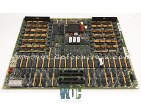
World Of Controls understands the criticality of your requirement and works towards reducing the lead time as much as possible.
DS200TCDAG2B - DIGITAL I/O BOARD is available in stock which ships the same day.
DS200TCDAG2B - DIGITAL I/O BOARD comes in UNUSED as well as REBUILT condition.
To avail our best deals for DS200TCDAG2B - DIGITAL I/O BOARD, contact us and we will get back to you within 24 hours.
Part No.: DS200TCDAG2B
Manufacturer: General Electric
Country/Region of Manufacture: United States of America
Product Type: Digital Input/Output Board
Series: Mark V
DS200TCDAG2B is a Digital Input/Output Board developed by GE under Mark V series. Several programmable read-only memory (PROM) modules and one microprocessor are both present on the board. Two 50-pin connectors and one block of ten LEDs are also included. 8 jumpers and 1 LED are included on it. The 50-pin connectors transfer signals to the DTBA and the DTBB boards mounted in the drive. Ribbon cables with a plugged-in one end are connected to the 50-pin connectors. The other end of the ribbon cable attaches to either the DTBA or the DTBB boards. Take note of the 50-pin ribbon cable routing inside the drive before removing the board to replace it, and keep it the same when you replace the board.
The JO1 and JO2 connections are used to send the contact output signals to the TCRA boards.
WOC experts are always available to help you with your GE turbine control component requirements. For more information, please contact WOC.
What is DS200TCDAG2B?
It is a Digital Input-Output Board developed by GE under the Mark V series.
The component has how many connectors?
On the terminal board, there are 8 hardware jumpers and 7 connectors.
How are contact inputs carried by the board?
Through the JR and JQ connections, it transports contact inputs from the DTBA and DTBB terminal boards.
Where do the card's contact outputs range?
Connectors JO1 and JO2 deliver contact outputs to the TCRA board.