World Of Controls understands the criticality of your requirement and works towards reducing the lead time as much as possible.
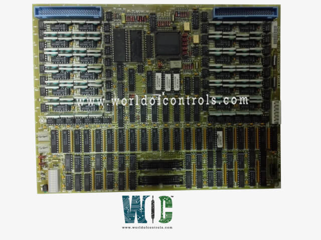
DS200TCDAG1ACA - Turbine Control Digital Auxiliary Board is available in stock which ships the same day.
DS200TCDAG1ACA - Turbine Control Digital Auxiliary Board comes in UNUSED as well as REBUILT condition.
To avail our best deals for DS200TCDAG1ACA - Turbine Control Digital Auxiliary Board, contact us and we will get back to you within 24 hours.
SPECIFICATIONS:
Part Number: DS200TCDAG1ACA
Manufacturer: General Electric
Series: Mark V LM
Product Type: Digital I/O Board
Weight: 1 lb 7 oz
Connectors: JR, JQ, JX1, JX2
On-board Configurable Hardware: 8 Jumpers (J1�J8)
Availability: In Stock
Country/Region of Manufacture: United States
Repair: 3-7 Days
Manual: GEH-6153
FUNCTIONAL DESCRIPTION:
DS200TCDAG1ACA is a Turbine Control Digital Auxiliary Board manufactured and designed by General Electric as part of the Mark V LM Series used in Gas Turbine Control Systems. The Digital IO Board (TCDA), which is situated in the Q11, Q51, and Q21 digital I/O cores, if any are present. The two TCRA boards' contact output (relay/solenoid) signals are processed by TCDA along with digital contact input signals from the DTBA and DTBB terminal boards. The TCQC board in R1, the CTBA terminal board in R5, and R2 if Q21 is installed all receive the signals via the IONET.
A serial communication network called the IO Network (IONET) links an IO Engine with any potential TCDA board. The TCDA boards in the digital cores (Q11, Q21, or Q51), in P1, all exchange data. The physical IONET connections, however, are made to the CTBA in R5 or the TCQC board in R1 and R2. The network only transmits data that is address-specific. Data is therefore routed to either the TCDA.
TCDA CONNECTORS:
JP - Distributes power from the TCPS board to the Q11, Q21, and Q51 cores, respectively, in the R1, R2, and R5 cores.
JQ - Connects to the DTBA board's JQR socket. transports the DTBA board's contact input signals to the TCDA board.
JR - Attaches to the DTBB board's JRR socket. is responsible for transporting the contact input signals from the DTBB board to the TCDA board.
JO1 - writes the relay/solenoid contact output signals to location 4 of the TCRA board. Not utilized in Q11 since TCQE in R1 directly controls the relays at location 4.
JO2 - writes the relay/solenoid contact output signals to location 5 of the TCRA board.
TCDA CONFIGURATION:
HARDWARE: The TCDA board has eight physical jumpers. For factory testing, use J1 and J8. Resistor IONET termination is for J2 and J3. The board's IONET ID is configured using J4, J5, and J6. Stall timer enable is J7. The hardware jumper settings for this board are described in Appendix A and on the operator interface's hardware jumper screen.
SOFTWARE: The I/O Configuration Editor on the HMI is where the I/O configuration constants for the contact input inversions are entered.
TCDA CONTACT INPUT CIRCUITS:
The TCDA board receives contact input signals from the DTBA and DTBB terminal boards through the JR and JQ connectors. These contact inputs are essential for monitoring and controlling various operational parameters. The board�s internal circuitry carefully processes each incoming signal, ensuring accurate detection of any state changes. Additionally, the circuitry incorporates timing mechanisms to manage transient signals or rapid fluctuations, preventing false triggers and ensuring reliable communication between the boards.
Once the TCDA board has processed and timed the contact signals, it transmits the information to the IONET system through the JX1 (or JX2) connector. This allows higher-level control and monitoring systems to interpret the inputs effectively. The behavior of these contact signals can also be modified through software, which provides the ability to invert the signals as required using configurable I/O variables. This flexibility ensures that the system can be tailored to meet specific operational requirements and integration needs.
WORLD OF CONTROLS maintains the largest inventory of GE Mark V LM Turbine Control System replacement parts, providing quick and reliable access to essential components. In addition to supplying new parts, we offer expert repair services for faulty boards and provide unused or rebuilt parts, all backed by a comprehensive warranty to ensure performance and reliability.
Our team of skilled engineers and technicians is available 24/7, ready to support all your OEM and automation needs, from troubleshooting and installation to technical guidance. For pricing, availability, or assistance with any parts or repairs, contact our team by phone or email, and we will ensure your operations continue smoothly with minimal downtime.
What is the function of the board?
The board processes digital contact input signals received from the DTBA and DTBB terminal boards. It monitors changes in the input states and times them accurately to prevent false triggers. After processing, the signals are transmitted to the IONET network for turbine control and monitoring. This ensures reliable communication with the turbine control system.
Which connectors are used for input and output?
Contact inputs are received through the JR and JQ connectors on the board. Processed signals are sent to the IONET network using the JX1 or JX2 connectors. These connections allow seamless integration with other turbine control system components. The board ensures that all signals are transmitted accurately.
Can the contact signals be inverted?
Yes, contact signals can be inverted through software using configurable I/O variables. This allows the system to adapt to different operational requirements. Signal inversion ensures flexibility in integrating the board with various turbine control setups. It also helps maintain proper logic interpretation in the control system.
What kind of onboard hardware does it have?
The board contains a microprocessor, multiple PROM modules, and a block of 10 LED indicators. It also has two 50-pin connectors and eight configurable jumpers for system settings. These components allow the board to process inputs and communicate with other control system elements efficiently. The LEDs provide visual status monitoring for troubleshooting and verification.